What is SMT?
SMT stands for surface mount technology. It is a method of circuit board assembly that involves mounting electronic components directly onto the surface of a printed circuit board (PCB). The components used in SMT have small, flat connecting pads or leads rather than long wire leads as in through-hole technology.
Some key advantages of SMT include:
- Smaller component size – allows for greater component density and miniaturization of electronic devices
- Faster assembly – components can be rapidly placed by automated pick-and-place machines
- Improved reliability – leads are less prone to damage during handling and assembly
- Reduced cost – higher yields with automation and fewer drilled holes needed
SMT components come in a range of standardized package types. Common examples include:
- Quad flat pack (QFP)
- Ball grid array (BGA)
- Chip scale package (CSP)
- Small outline integrated circuit (SOIC)
- Thin small outline package (TSOP)
SMT Circuit Board Design Considerations
Designing a circuit board for SMT requires some different considerations from through-hole PCBs:
Component Spacing
As components are mounted directly on the board surface, spacing them correctly is critical. Components must have sufficient clearance between their bodies and leads to prevent short circuits. The gaps between components must also allow for solder paste application and reflow.
Pad Size and Shape
Pads must be the right size and shape to match the leads or ball grids of SMT components. Too small and the joint may fail, too large can lead to solder bridging between pads.
Thermal Management
With higher component density, managing heat dissipation on SMT boards is important. Thermal vias, pads, and planes help conduct heat away from components.
Board Finish
The board’s surface finish impacts solder wetting, adhesion, and long-term reliability. Common finishes like ENIG, Immersion Silver provide excellent solderability for SMT.
Solder Mask
A solder mask defines the solderable areas on the PCB surface. It prevents solder bridging and protects traces from corrosion.
SMT Assembly Process
Assembling SMT boards requires specialized equipment and processes:
Solder Paste Printing
Solder paste containing powdered solder and flux is dispensed onto pads through stencils. This “prints” precise amounts of solder paste where components will be placed.
Component Placement
Pick and place machines use vacuum nozzles to quickly and accurately pick components from reels or trays and place them onto the solder paste.
Reflow Soldering
The board passes through a reflow oven heating the solder paste to melt it and form solder joints to attach components. Different temperature profiles are used depending on solder alloy.
Inspection and Testing
Quality control checks like visual inspection and in-circuit testing are done to verify proper assembly and catch any defects. X-ray inspection can check for hidden solder joint issues.
Conformal Coating
A protective polymer coating may be applied to shield boards from moisture, contaminants, and corrosion.
Common SMT Components
Here are some of the most prevalent component types used in SMT assembly:
Passive Components
- Resistors – Fixed, variable, trimmer, terminator
- Capacitors – Multilayer ceramic, tantalum, polymer, chip
- Inductors – Wirewound, multilayer, chip
Active Components
- ICs – Digital, analog, mixed signal, microprocessors
- Transistors – MOSFETs, BJTs
- Diodes – Switching, Zener, Schottky, LEDs
Other Components
- Connectors – Board-to-board, board-to-cable
- Crystals and Oscillators – For timing
- LEDs – Lighting and indication
- Sensors – Temperature, pressure, optical
| Component | Package Type | Description |
|---|---|---|
| Resistor | 0402, 0603, 0805, 1206 | Thin rectangular ceramic body with metallized end caps. Values marked with numerals. |
| Capacitor | 0402, 0603, 0805, 1206, 1812 | Rectangular ceramic body with metallized end caps. Values marked. |
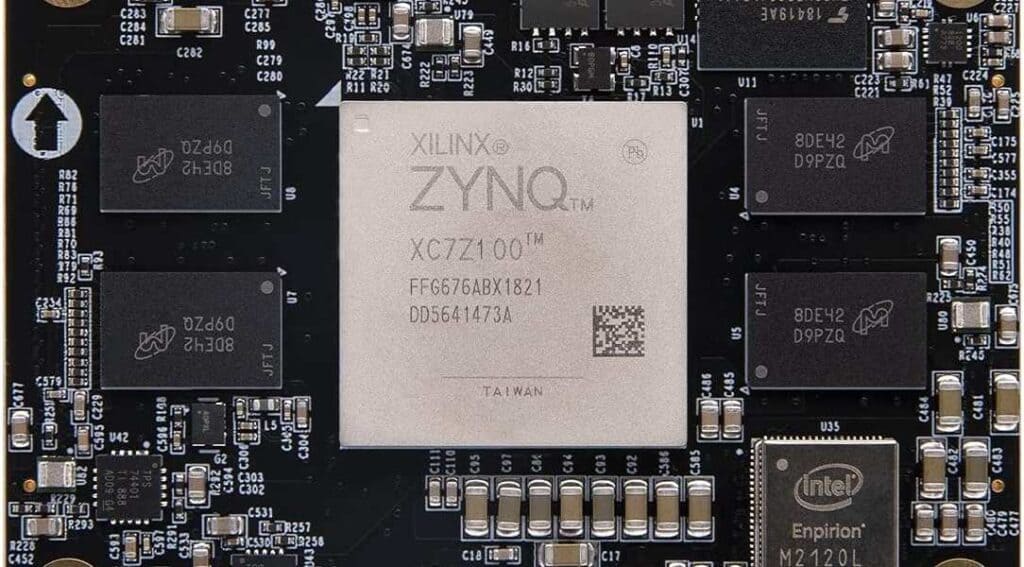
| IC | QFP, TSOP, SOIC | Flat plastic body housing silicon die. Leads on sides. |
| Transistor | SOT-23, SOT-363 | Small plastic case with 3 inline leads. |
| Diode | SOD-123, SOD-323 | Small glass body with wire leads. Black band marks cathode. |
| LED | 0603, 0805 | Rectangular plastic body with two short leads. |
Benefits of Common SMT Packages
- 0402 – Small size allows high density. Can be challenging to handle.
- 0603 – Good balance of small size and ease of assembly. Very common.
- 0805 – Larger but still small. Easier for pick and place.
- QFP – Pitch options for high to moderate density. Low inductance.
- BGA – Extremely dense I/O counts. Short traces and good performance.
- SOIC – Bread-and-butter IC package. Low cost, widely available.
SMT Rework and Repair
Despite quality controls, sometimes faults occur requiring SMT rework and repair:
- Manual Soldering – Using fine tip irons and microscopes to remove/replace components. High skill needed.
- Solder Paste and Hot Air – Applying new paste and using air tools to reflow joints. Lower skill threshold.
- Specialty Rework Systems – Advanced systems with thermal profiling for easy, repeatable rework of components like BGAs and SMT connectors. High capital cost.
- Board Repair Systems – Automated optical inspection finds defects, then specialized tools remove solder bridges, rerate pads, and deposit solder paste for rework. Expensive equipment.
Careful process control during initial assembly is still the best way to avoid costly SMT rework!
Frequently Asked Questions
What are some challenges with SMT manufacturing?
Some challenges with SMT production include:
- High capital equipment costs for pick-and-place and reflow processes
- Need for very clean, controlled environments to prevent defects
- Difficulty inspecting undersides of components like BGAs for quality issues
- Thermal stresses on components during soldering
- Repair and rework of SMT can be difficult and time consuming
How small can SMT components be?
SMT component sizes have become progressively smaller over time, currently reaching down to packages as tiny as 01005 (0.4mm x 0.2mm) for simple passive components like resistors and capacitors. The lower limit is driven by factors like manufacturability, handling issues, susceptibility to damage, and minimum feature sizes for PCB fabrication and solder joints.
Are SMT boards as reliable as through-hole?
Properly designed and assembled SMT boards can actually exceed the reliability of equivalent through-hole designs. Avoiding long wire leads reduces risks of mechanical damage and oxidation. Advanced solder alloys and board finishes provide highly reliable solder joints. And SMT lends itself well to automatic optical inspection and testing to screen early life defects.
How are components mounted on bottom side of board?
For double-sided SMT boards, specialized equipment allows placement of bottom side components in a single pass or “all-at-once” process. Components are fed upside down into the pick-and-place machine so they are oriented correctly on the bottom side. Optical alignment systems compensate for board warpage and precisely place the underside components.
Does hand soldering work for SMT?
Hand soldering SMT devices is very challenging and really requires excellent manual skills along with tools like solder paste and microscope. It can be done successfully for repairs and rework in low volume cases. But for manufacturing, the speed, precision, and repeatability of automated pick-and-place and reflow methods is far superior.


0 Comments