
Flexible printed circuit boards (FPCBs), also known as flex circuits, are made from flexible polymer substrates that allow the board to bend and flex. FPCBs are commonly used in small electronics like cameras, mobile devices, printers, and medical equipment where space is limited and flexibility is required. Assembling flex PCBs requires some specialized considerations compared to rigid PCB assembly.
Flex PCB Assembly Process Overview
The basic assembly process for flex PCBs includes:
- Design and fabrication of the flex PCB
- Attachment of electronic components to the board
- Connecting and soldering components
- Testing for defects
- Final assembly into the end product
Each step is critical for producing a quality, functional flex assembly. Here is an overview of the key stages:
Flex PCB Design
The design process defines the layout, materials, layers, and dimensions of the flex PCB based on requirements. Some key design considerations include:
- Bend radius – The minimum bend radius dictates the flexibility. Smaller bend radii allow tighter folds but increase chances of damage.
- Layers – FPCBs can be single or double-sided. Multilayer boards are also used for more complex circuits.
- Conductors – Copper traces carry current. Narrower traces allow tighter spacing but can limit current capacity.
- Stiffeners – Special stiff board may be layered in for sections that do not require flexing.
- Connectors – Connectors must be selected to match pitch and dimensions.
Flex PCB Fabrication
Once the design is finalized, the flex boards are fabricated. The basic process includes:
- Producing the conductive copper layers
- Adding dielectric polymer layers
- Laminating layers together under heat and pressure
- Etching away copper to form circuit traces
- Printing solder mask and markings
- Punching holes, slots, or cutouts if needed
The fabricated boards are tested before release to ensure quality and accuracy.
Component Attachment
Attachment of components to the flex board is a precision process. Some methods include:
- Soldering – Leads are soldered to pads on the board. Not ideal for flexing.
- Conductive adhesive – Adhesives containing conductive particles secure components. Allows flexing.
- Mechanical assembly – Clips, pins, or compression fits hold components. Removable.
Soldering
Soldering electrically connects the attached components. Many methods are used:
- Hand soldering – For prototyping or rework. Not efficient for volume.
- Wave soldering – Board passes over a wave of molten solder. For high volume.
- Reflow soldering – Solder paste is applied then melted in an oven. Most common method.
Testing and Inspection
Thorough testing ensures the flex board assembly functions as intended:
- Automated optical inspection – Checks for missing or defective components and solder issues.
- In-circuit testing – Electrical tests verify connectivity and identify faults.
- Functional testing – Validates proper functioning for the product application.
Final Assembly
The finished flex assembly is integrated into the overall product during final assembly. This may involve:
- Connecting cables, wires or mating connectors
- Mounting or fastening the assembly into the product enclosure
- Performing end-product testing and diagnostics
- Final calibration or configuration
Careful handling is imperative during final assembly to avoid damaging the flexible board.
Flex vs. Rigid-Flex PCB Assemblies
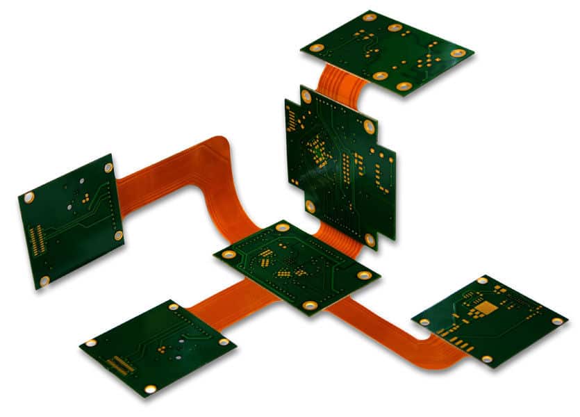
There are two main types of circuit boards that use flexible properties:
- Flex PCBs – Entirely flexible with no rigid sections. Can be bent, folded, or rolled.
- Rigid-flex PCBs – Combines rigid board with flexible connections. Rigid areas provide structure and mounting.
Here is a comparison between flex PCB and rigid-flex PCB assemblies:
| Feature | Flex PCB Assembly | Rigid-Flex PCB Assembly |
|---|---|---|
| Board materials | Entirely flexible polymer | Rigid fiberglass for stiff sections |
| Layer structure | Flexible layers only | Rigid layers combined with flexible layers |
| Components | Mainly surface-mount devices | Surface-mount and through-hole components |
| Assembly methods | Mostly reflow soldering | Wave or reflow soldering |
| Use cases | Tight spaces, dynamic flexing | Complex rigid/flex structures |
| Cost | Lower | Higher due to complex fabrication |
In summary, flex PCBs provide pure flexibility while rigid-flex PCBs combine that with the sturdiness and stability of rigid sections. Rigid-flex requires more complex design and fabrication for both types of sections.
Quality Control in Flex PCB Assembly
Stringent quality control is essential during each step of the flex PCB assembly process. Some key quality control measures include:
Materials inspection – Inspect raw PCB materials for defects prior to manufacturing. Verify properties like flexibility and dielectric strength.
Process monitoring – Control process parameters like temperature and pressure during lamination, soldering, and other steps to stay within specified ranges.
First article inspection – Thoroughly test a representative sample board from the first manufacturing batch before full production. Confirm electrical operation, dimensions, and functionality.
AOI inspection – Automated optical inspection of assembled boards detects issues like missing components, misalignments, and solder defects.
Electrical testing – Verify electrical connectivity and circuit operation using fixture-based in-circuit testing or flying probe testing.
Dimensional inspection – Check conductor widths, spacing, hole sizes, and other physical dimensions match specifications.
Functional testing – Validate the completed assembly operates properly before integration into the end product.
Implementing robust quality control and inspections ensures each flex PCB assembly meets the highest standards before delivery. This prevents defective products and avoids costs associated with reworking and rectifying issues after final assembly.
Flex PCB Assembly Challenges
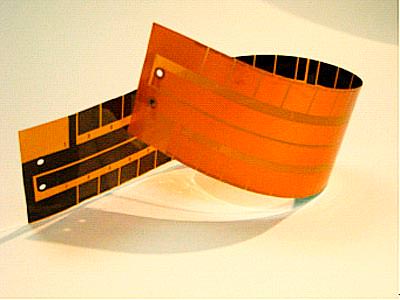
Assembling flex PCBs poses some unique challenges compared to standard rigid boards:
- Small features – Thin traces and spaces require precision assembly with little margin for error.
- Flexing stress – Bending or folding can damage traces and joints if not designed properly.
- Component attachment – Adhesives and fasteners must withstand flexing forces without detaching.
- Via reliability – Plated through holes and other vias can crack under bending stresses.
- Warping – Flexible boards can warp during heating processes like soldering.
- Testing – Probing and inspection is difficult on thin, easily damaged flex circuits.
Managing these challenges starts with design to maximize reliability and minimize stresses. The assembly process must use specialized procedures tailored for flex boards. Operators need proper training on the nuances of handling and working with flexible PCBs. With careful planning and execution, complex high-density flex circuits can be successfully assembled for mission-critical applications.
Applications of Flex PCB Assemblies
Thanks to their small size and dynamic flexibility, flex PCB assemblies are used across a wide range of industries and products including:
- Mobile phones, tablets, wearables
- Digital cameras
- Notebook displays and LCD monitors
- Printers and photocopiers
- Hard disk drives
- Medical equipment
- Automotive electronics
- Robotics and drone components
- Industrial machine controls
Within these products, flex PCB assemblies provide reliable connectivity for applications like:
- Interconnects between rigid PCBs
- Cable replacement for signals and power
- Dynamic flexing wiring harnesses
- Circuits for moving components
- Space-saving structures folded into 3D shapes
Continuing improvements in flex PCB technology, materials, and assembly processes will enable even more creative applications in the future.
Flex PCB Assembly FAQ
Here are answers to some frequently asked questions about flex PCB assembly:
What are the main steps in the flex PCB assembly process?
The key steps are PCB fabrication, component attachment, soldering, testing/inspection, and final product integration. Precision and care is required at each stage to avoid damage.
How are components attached to flexible PCBs?
Common attachment methods are soldering, conductive adhesives, mechanical assembly, and compression fits. The method depends on reliability requirements and expected flexing.
What defects can occur in flex PCB assemblies?
Common defects include cracked joints and traces, warping, missing components, misaligned parts, inadequate clearance, and improper terminations or connections.
How is rework performed on flex PCB assemblies?
Rework for defects or modifications is very challenging. It may require complete removal and replacement of affected components and conductors.
Can flex PCB assemblies be tested using automatic test equipment?
Yes, fixtures allow positioning the flexible boards for access to testpoints during in-circuit testing. Flying probe testers are also commonly used.