Surface mount technology (SMT) has revolutionized the electronics manufacturing industry. Surface mount devices (SMDs) and PCB assemblies allow for miniaturization and high component density, improving reliability and reducing costs. This comprehensive guide covers everything you need to know about surface mount PCB design, assembly, and rework.
What is a Surface Mount PCB?
A surface mount PCB uses surface mount components that are soldered directly to the surface of the board without leads inserted through holes. Traditional through-hole components use wire leads that pass through holes drilled in the PCB and are soldered on the opposite side.
Key differences between through-hole and SMT components:<table> <thead> <tr> <th>Through-Hole</th> <th>Surface Mount</th> </tr> </thead> <tbody> <tr> <td>Leaded components with wire leads</td> <td>Leadless chip components</td> </tr> <tr> <td>Larger component size</td> <td>Smaller component size</td> </tr> <tr> <td>Lower component density</td> <td>Higher component density</td> </tr> <tr> <td>Only one side can be populated</td> <td>Both sides can be populated</td> </tr> <tr> <td>Manual assembly</td> <td>Automated assembly</td> </tr> </tbody> </table>
SMT components come in standard sizes from 01005 (0.4mm x 0.2mm) up to 70mm+ square packages. Common types include:
- Passives – Resistors, capacitors, inductors
- Actives – ICs, transistors, diodes
- Electromechanical – Connectors, switches, relays
- Packages – QFP, SOIC, BGA, CSP
The smaller size and leadless design of SMT components allows for greater PCB miniaturization and component density. Modern consumer electronics would not be possible without the advantages of surface mount technology.
Benefits of SMT
There are many important benefits of SMT over through-hole technology:
- Smaller size – Huge reduction in component footprint and overall PCB size.
- Light weight – Less mechanical stress on PCB with fewer drilled holes.
- High density – More components can be fitted on a single PCB.
- Reliability – Leadless construction is more resistant to vibration and shock.
- Cost – Automated assembly reduces manufacturing costs.
- Double-sided – Components can be placed on both sides of the PCB.
- Simplified assembly – Faster, easier automated SMT assembly.
- Improved performance – Shorter signal traces improve high frequency operation.
- Flexibility – SMT supports advanced packaging techniques.
- Environmental – Leadless components are more eco-friendly.
The tradeoff is that SMT boards require more complex design and assembly equipment. But the advantages far outweigh the disadvantages for most applications.
SMT PCB Design Considerations
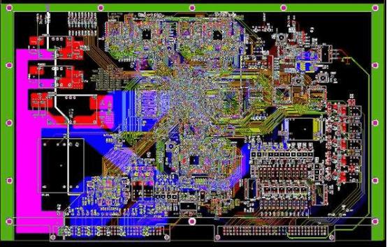
Designing a surface mount PCB requires careful planning to accommodate the assembly requirements and capabilities. Here are some key SMT design considerations:
Component Footprint – Chip components have unique land patterns that must be followed. Consult manufacturer datasheets for the correct footprints.
Package size – Select component packages small enough to fit space requirements. Pay attention to height restrictions.
Layout density – Decide how components will be grouped to optimize space while allowing assembly access.
Reflow profile – Adhere to soldering temperature guidelines based on component material properties.
Assembly access – Provide sufficient clearances for pick and place heads, clips, and other assembly tools.
Testpoints – Include testpoints linked to component pads for improved debugging and rework.
Solder mask – Define solder mask openings slightly larger than pad sizes. This accounts for tolerances.
Solder paste – Use solder paste openings slightly smaller than pads to prevent bridging.
There are also important rules to follow in laying out surface mount devices:
- Component orientation – All polarized components must have the correct orientation.
- Package symmetry – Maintain symmetry on opposite sides for double-sided reflow.
- Fine pitch parts – Allow extra tolerances for placing and soldering fine pitch components.
- Mixed placement – Separate large and small components into groups for optimized assembly.
- Thermal relief – Use thermal relief connections to minimize solder joint stresses.
- Fiducials – Place fiducials for accurate component positioning.
Following SMT design guidelines will ensure a PCB that functions correctly and can be efficiently assembled.
SMT Assembly Process
Assembling a SMT PCB involves solder paste deposition, component placement, and solder reflow:
Solder Paste Printing – Solder paste is deposited on pads through stencils using squeegees. Stencils are laser cut metal masks that match the PCB footprint patterns. Proper alignment and print pressure are critical.
Component Placement – Robotic pick and place machines populate components onto the solder paste. High speed vision systems precisely locate pads and align parts. Parts can be placed on one or both sides.
Reflow Soldering – The assembled board passes through a reflow oven to heat solder paste above liquidus temperature. Solder joints form as the assemblies cool down, securing components. Different temperature profiles are used based on component properties.
Inspection – Automated optical inspection (AOI) systems verify component placement and solder joints after reflow. X-ray inspection can also be used to inspect internal features like BGA connections.
Testing – Electrical testing checks for manufacturing defects like opens, shorts, missing components or misorientation. Flying probe and bed of nails testers provide automated circuit testing.
Conformal Coating – A protective coating material can be applied to prevent environmental damage. Common options include acrylic, urethane, silicone and parylene.
Properly following SMT assembly procedures results in high production yields and reliable PCB assemblies.
SMT Rework and Repair
Despite quality controls, it may still be necessary to rework solder connections or replace components on assembled SMT boards. Common SMT rework processes include:
- Soldering iron – Small SMD components can often be repaired by hand soldering. Use proper tip temperature and flux.
- Solder wick – Braided copper wick can remove solder bridges and excess solder from joints.
- Hot air station – A temperature controlled air stream heats joints for component removal and soldering. Vacuum pickup tools manipulate parts.
- Repair kits – Self-contained systems have hot air tools integrated with microscope viewing.
- Automated dispensers – Precision robots can apply solder paste and adhesives for rework.
- AOI systems – Inspect repairs under magnification to ensure proper soldering.
It takes training and experience to reliably rework surface mount assemblies. Proper tools, technique and inspection methods are needed for success.
SMT vs Through Hole Assembly
There are tradeoffs between SMT and through-hole assembly processes:<table> <thead> <tr> <th></th> <th>SMT Assembly</th> <th>Through-Hole Assembly</th> </tr> </thead> <tbody> <tr> <td>Board size</td> <td>Smaller</td> <td>Larger</td> </tr> <tr> <td>Component size</td> <td>Smaller 01005 – 70mm+ </td> <td>Larger</td> </tr> <tr> <td>Speed</td> <td>Faster automated</td> <td>Slower manual</td> </tr> <tr> <td>Soldering</td> <td>Reflow oven</td> <td>Wave or hand soldering </td> </tr> <tr> <td>Testability</td> <td>In-circuit test</td> <td>Easy probe access</td> </tr> <tr> <td>Rework</td> <td>Microscope & hot air tools</td> <td>Soldering iron</td> </tr> <tr> <td>Costs</td> <td>Higher startup costs</td> <td>Lower startup costs</td> </tr> </tbody> </table>
SMT is preferred for modern electronics due to the size, weight and performance benefits. But through-hole still has advantages for large components, simple circuits, and low volume production. Many designs incorporate both SMT and through-hole assembly.
Pros and Cons of SMT
Here is a summary of the key advantages and disadvantages of surface mount technology:
Pros:
- Small size and high density
- Lightweight and reliable
- Automated assembly
- Lower manufacturing costs
- Improved electrical performance
- Double-sided component placement
- More environmentally friendly
Cons:
- More complex PCB design rules
- Solder joint defects can be difficult to detect
- More expensive assembly equipment
- Rework is challenging without proper tools
- Tombstoning defects require experience to prevent
- Fine pitch parts need precision assembly
Conclusion
Surface mount PCB technology provides the capability to produce smaller, lighter, and higher performing electronics. With SMT, mobile consumer gadgets can pack thousands of components into a compact, reliable package. The tradeoff is increased design complexity and the need for advanced assembly machinery. But with the right knowledge and processes, Engineers can take full advantage of the benefits of surface mount PCBs.
FAQs
1. What is the difference between through-hole and SMT components?
The main differences are that SMT components are leadless with contacts on the underside, much smaller in size, and solder directly to the surface of the PCB without wire leads going through holes. Through-hole parts use leaded components with wires that fit through drilled holes and are soldered on the opposite side.
2. What are some common SMT component package types?
Some popular surface mount package types are:
- QFP (Quad Flat Pack) – Square ICs with leads on all 4 sides
- SOIC (Small Outline IC) – Rectangular ICs with leads on 2 sides
- SOP (Small Outline Package) – IC package similar to SOIC
- TSOP (Thin Small Outline Package) – Thin SOIC version
- TQFP (Thin Quad Flat Pack) – Thin version of QFP
- BGA (Ball Grid Array) – Square IC package with solder ball contacts on bottom
3. How does solder reflow work?
Solder reflow is the process of heating an assembled PCB to melt solder paste deposits so that components are permanently soldered in place. Reflow ovens heat the assemblies with convection and infrared radiation. The temperature follows a thermal profile to activate flux, evaporate solvents, reflow solder, and cool down. The profile must be matched to the solder alloy being used.
4. How do you inspect solder joints?
Key aspects in inspecting solder joint quality are proper wetting and fillet shapes, acceptable voiding, and sufficient joint height. Other checks include verifying pad coverage, meniscus shape, and the absence of defects like cracks, icicling, or tombstoning. Optical inspection and x-ray imaging are common methods used.
5. What are common SMT rework methods?
Typical SMT rework techniques include:
- Soldering iron – For small components
- Solder wick – Removing excess solder
- Hot air station – Heating for desoldering and soldering
- Microscope – Magnified views for inspection
- Vacuum pickup – Manipulating tiny components
- Syringe dispensers – Precision solder and glue deposition


0 Comments