Introduction to Through Hole Assembly
Through hole assembly (THA) is a method of assembling printed circuit boards (PCBs) by inserting component leads into holes drilled in the board and soldering them in place on the opposite side. Also known as plated through hole (PTH) assembly, it was the predominant technology used to assemble circuit boards prior to the introduction of surface mount technology (SMT) in the 1980s.
Despite the shift toward SMT, THA remains an essential manufacturing technique today due to its advantages:
- Components are held securely in place by soldered leads rather than just solder pads
- THA boards can accommodate higher power/current devices
- Components are easy to replace by desoldering
- No special soldering equipment needed beyond a soldering iron
- Lower cost compared to SMT for low volume or prototype runs
In this comprehensive guide, we will explore everything you need to know about specifying, designing, and assembling THA PCBs.
THA Design Considerations
Several factors must be considered when designing a PCB for through hole assembly:
Component Selection
- Through hole components – resistors, capacitors, connectors etc with wire leads for TH insertion.
- Leaded packages – ICs, transistors etc are available in leaded packages designed for TH mounting.
- Pin spacing – Components must have lead spacing that matches PCB hole spacing.
Hole Size
- Hole diameter slightly larger than lead diameter for easy insertion.
- Typically 0.4mm to 1.0mm diameter holes.
- Too large increases risk of solder wicking up hole.
Hole Spacing
- Hole spacing matches component lead spacing.
- Varies based on component size – 2.54mm is common.
- Sufficient pad size around holes for soldering.
Trace Routing
- Vias and traces routed between holes on inner board layers.
- No traces in pad area around holes.
Board Thickness
- Standard 1.6mm PCB sufficient for most TH components.
- Thicker 2.4mm boards used for high reliability or if through hole components mounted on both sides.
PCB Land Patterns and Layout
The PCB land pattern for through hole components consists of metal pads with holes drilled at the center:
With careful layout, TH assembly can achieve high component density. Some guidelines include:
- Place components on both sides to maximize space.
- Use vias to route traces between layers.
- Place decoupling capacitors close to IC pins.
- Minimize trace length for high frequency or current signals.
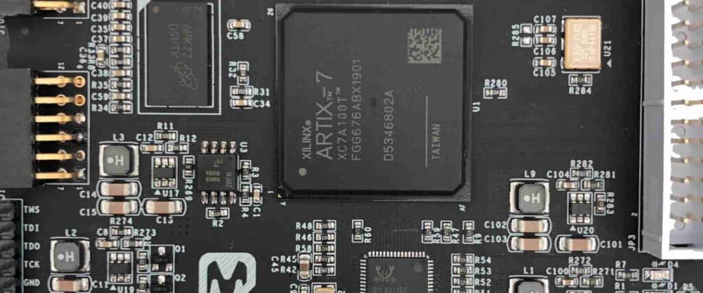
Here is an example of a dense THA PCB layout:
PCB Fabrication
Manufacturing THA boards involves several fabrication processes:
Drilling
- Holes are drilled through the copper clad laminate using CNC mechanical or laser drills.
- Most drills can achieve hole sizes down to 0.15mm and ±0.05mm accuracy.
Plating
- Boards are plated with copper to connect inner layers and coat hole walls.
- Electroless plating coats board with thin copper layer.
- Electroplating grows copper thickness to specified 1oz/ft2 or 2oz/ft2 weight.
Masking
- Photoimageable solder mask applied around pad areas.
- Mask defines solderable areas and provides insulation.
- LPI and dry film are common solder mask types.
Finishing
- Hasl lead-tin solder coating or immersion gold finish applied.
- Provides solderability for component leads.
THA Assembly Process
After the PCB fabrication and solder paste stencil are complete, THA can begin:
- Paste application – Solder paste is applied through stencil openings onto pads.
- Component placement – Components inserted into boards with leads through holes.
- Soldering – Reflow oven or wave soldering bonds leads to pads.
- Cleaning – Flux residue cleaned using solvents.
- Inspection – Boards are optically inspected for defects or x-rayed for hidden issues.
- Conformal coating – Protective coating applied for environmental protection.
Here is a snapshot of the TH assembly l
Quality Control
Several checks are performed to ensure quality of THA boards:
- Visual inspection of solder joints, spacing, polarity.
- J-STD-001 solder joint requirements.
- IPC-A-610 soldering acceptance criteria.
- Netlist testing matches board connectivity to schematic.
- Flying probe testing checks electrical shorts and opens.
- Functional testing verifies circuit operation.
Advantages and Disadvantages of THA
Through hole assembly offers some benefits but also has limitations compared to SMT:
Advantages
- Mature, low cost process
- Components held securely by leads
- Easy repair and rework
- No special equipment beyond soldering iron
- Suits high power components
Disadvantages
- Lower component density than SMT
- Only usable with leaded components
- Larger board size required
- Labor intensive process
- Not practical for ultra-fine pitch ICs
Recent THA Technology Innovations
Despite the predominance of SMT, innovations in THA continue:
- Laser vias drill holes with no contact for improved quality.
- X-ray drilling captures inner layer images for very high density holes.
- Plasma treatment enhances hole wall solderability.
- Embedded components improve density by incorporating TH devices within the board.
- Automated optical inspection (AOI) of TH joints increases quality.
When to Use Through Hole Assembly
Here are some of the most common applications still using THA technology today:
High Power Circuits
TH components can handle higher power and current levels than SMT. THA is prevalent in power electronics like motor controls, power supplies, and LED drivers.
High Frequency Radio Boards
The leads of TH components provide better grounding and shielding for RF boards like WIFI, radar, and cellular infrastructure.
High Reliability Applications
Aerospace, defense, and medical products often stipulate THA due to proven reliability. Common with large, leaded ICs or connectors.
Serviceable or Upgradeable Products
THA allows components to be individually replaced. Useful for test equipment, industrial controls, and devices with field upgrades.
Low Volume or Prototype
For short runs, THA avoids the high tooling cost of SMT stencils and programming.
Conclusion
Although SMT now dominates modern PCB production, through hole assembly still powers a wide array of electronic devices today. With attention to design practices and assembly processes, THA provides a cost-effective solution for many applications. Continued innovations also promise to expand THA capabilities for future needs.
Frequently Asked Questions
What are the main advantages of through hole assembly?
The primary advantages of THA are:
- Components held securely by soldered leads
- Ability to use high power leaded components
- Easy rework and field replacement of components
- Mature, low cost manufacturing process
- No need for advanced SMT soldering equipment
Is through hole still used today?
Yes, THA remains widely used today despite the popularity of SMT. It is prevalent in cost-sensitive, high reliability, low volume, or high power products where SMT is not well suited. THA is also used for attaching larger connectors or other TH components to SMT boards.
What are recommended PCB hole sizes?
Common hole sizes are:
- 0.4mm – Used for IC pins or small component leads
- 0.6mm – For standard leaded components like resistors
- 0.8mm to 1.0mm – For heavier gauge wire or connectors
- 1.2mm to 1.5mm – For high current power components
Hole size should be matched to lead diameter with sufficient clearance for insertion.
How can I determine the optimal hole spacing?
Hole spacing should match the lead spacing of your chosen TH component package. Common spacings are:
- 2.54mm (0.1″) – For standard DIP ICs, resistors, capacitors
- 5.08mm (0.2″) – Some larger leaded ICs
- 7.62mm (0.3″) – For larger power components
Check component datasheets for exact lead spacing and position.
What are recommended PCB trace widths?
Common PCB trace widths are:
- 0.25 mm – For general purpose digital and analog signals
- 0.5 mm – For power signals up to 2A current
- 1 mm – For high power traces over 2A
- 0.125 mm – For high speed digital signals below 10MHz
Wider traces help minimize resistance for power signals. Narrow traces reduce capacitance for fast digital signals.


0 Comments