Introduction to Surface Mount Technology
Surface mount technology (SMT) is a method of assembling electronic circuits where the electronic components are mounted directly onto the surface of printed circuit boards (PCBs). This manufacturing process represents a major advancement over the previous through-hole technology, where component leads were inserted into holes drilled in the PCB.
The change to surface mount packaging began in the 1960s and expanded rapidly in the late 1980s and early 1990s. Today, the vast majority of manufactured electronic circuit boards are assembled using SMT. Some key advantages of SMT include:
- Smaller size: SMT components take up less space, allowing for smaller and lighter end products.
- Simpler assembly: Automated SMT assembly lines are faster and cheaper than manual through-hole assembly.
- Improved performance: Smaller components equate to shorter circuit paths and faster circuits.
- Lower cost: Smaller components are cheaper to produce and SMT automation reduces assembly costs.
Some of the common types of surface mount device (SMD) components used in SMT include:
- Resistors and capacitors – These basic components come in standardized case sizes, allowing them to be easily handled by SMT machines.
- Integrated circuits (ICs) – Chips come in various surface mount packages such as flat packs, quad-flat packs (QFP), and ball grid arrays (BGA).
- Connectors – SMT connectors don’t have protruding pins, allowing them to mate directly with the PCB.
In this guide, we will explore the SMT assembly process step-by-step, covering key considerations in SMT manufacturing.
Overview of the Surface Mount Assembly Process
The surface mount assembly process can be broadly divided into three main stages:
1. SMT PCB Design and Fabrication
- PCB layout with SMT footprint components
- Panelization of PCBs for manufacturing
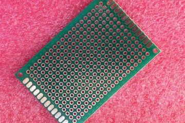
- Fabrication of bare PCBs
2. SMT Component Preparation
- Procurement of components
- Component packaging (taping and reeling)
- Solder paste stencil fabrication
3. SMT PCB Assembly
- Solder paste application
- Component placement
- Reflow soldering
- Inspection and testing
We will now look at each of these stages in more detail.
SMT PCB Design and Fabrication
PCB Layout
The first step is designing the PCB layout and schematics with SMT footprints. Some key principles for SMT design include:
- Use surface mount footprints for all components
- Minimize trace lengths between components
- Allow sufficient clearance between components
- Use vias and planes for thermal management
- Optimize layout for automated assembly
Modern PCB design software makes the process of working with SMT components highly streamlined. Libraries contain the SMT footprints for every commonly used component.
Panelization
For mass production, individual PCBs are arranged in a panel frame containing multiple PCBs in an array. The panel is the basic unit that gets moved through SMT assembly. Panelization aims to maximize the number of boards per panel, minimize tooling costs, and account for board stresses during fabrication and assembly.
After SMT assembly, the panels are routed to separate into individual boards. V-scoring or tab-routing techniques are used to facilitate this depanelization.
PCB Fabrication
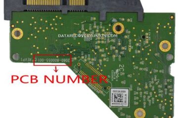
The fabricated bare boards have finished copper traces, coated surfaces, protective solder mask, and exposed solder pads. Multi-layer boards may contain buried vias and internal power or ground planes. High density interconnect (HDI) technology supports the fine traces and spaces required by advanced SMT components.
SMT Component Preparation

Component Procurement
The bill of materials (BOM) lists the quantity, reference designators, specifications, and sources for all the required components. Components may be sourced from electronics distributors or directly from manufacturers. Strategic sourcing principles are applied to balance cost, quality, and supply chain factors.
Components ordered from reputed sources are less likely to be counterfeit. Any high value or critical components should have anti-counterfeiting measures applied by the manufacturer.
Taping and Reeling
Most SMT components are supplied in tape and reel packaging, which are feeding mechanisms designed for automated component placement.
- Tapes consist of pockets that hold the components and cover tape to retain them in place.
- Reels are spools that hold the tape and provide easy transportation and mechanical feeding.
Tapes come in standardized widths of 8mm, 12mm, 16mm, 24mm, 32mm, and 44mm. Reels follow EIA-481 standards for diameter, mounting holes, and other parameters.
Solder Paste Stencils
The solder paste stencil is a metal sheet laser cut with apertures matching the solder pads on the PCB. During solder paste printing, it allows precise deposition of solder paste on solder pads. Stencils are typically made from stainless steel or nickel-plated brass for durability and solder paste compatibility.
Advanced laser cutting allows stencil apertures to match even the most minute pad geometries. Stencil thickness is chosen based on solder paste type and pad pitch. Typical thickness is 100-150 μm. Stencils may be coated to reduce solder paste clogging.
SMT PCB Assembly
SMT assembly consists of sequential steps using specialized equipment. The steps include:
Solder Paste Printing
The stencil is aligned over the PCB and a squeegee spreads solder paste across the stencil surface, forcing it through apertures onto pads. After paste printing, the stencil is removed and the PCB proceeds to component placement.
Component Placement
Pick and place machines precisely place surface mount components onto the solder paste. Feeders line up the components which get picked by vacuum nozzles and placed on the board. Machines contain multiple nozzles and feeders for high speed placement.
Vision systems accurately locate board fiducials and identify components before placement. Boards stay fixed on the conveyor while feeders rotate to pick components. Some key capabilities of modern pick and place machines include:
- High speed capability of over 100,000 chip placements per hour
- Support for component sizes from 01005 chips up to 50×50 mm sizes
- Feeder capacity up to 1000+ 8mm or 12mm tape reels
- Support for tray, stick, and bulk feeding of odd components
- Onboard auto vision alignment and inspection
Reflow Soldering
After component placement, the boards pass through a reflow oven to solder all joints simultaneously. The assembly enters a temperature controlled conveyor belt. Multiple heat zones raise the temperature profile to:
- Evaporate solder paste solvents
- Initiate solder flow
- Peak above liquidus temperature
- Cool down to solidify solder joints
The ideal thermal profile depends on solder paste alloy, board density, and component types. Common reflow methods include:
- Convection ovens: Heat is applied using circulating hot air
- Infrared ovens: IR panels emit radiant heat energy
- Vapor phase: Boards get immersed in an evaporating fluorocarbon liquid
- Laser soldering: A laser beam provides rapid localized heating
Inspection and Testing
Post-reflow inspection ensures quality and reliability:
- Visual inspection: Operators or automated optical inspection (AOI) machines look for visible defects
- X-Ray inspection: X-ray imaging detects hidden solder joint issues
- ICT testing: Checks for electrical shorts, opens, and misconnections
- Functional testing: Confirms boards operate as designed
Failed boards can be repaired by reworking solder joints. Debugging tools like JTAG boundary scan test for faults in complex assemblies.
Coating and Finishing

Additional steps may add protective coatings or finalize the assembly:
- Conformal coating shields against moisture, dust, and corrosion
- Potting and encapsulation protects with polymeric compounds
- Board routing singulates multi-up panels into individual boards
This completes the surface mount technology assembly process. Finished boards are cleaned, packed, and shipped to customers.
Key Considerations in SMT Assembly
Here are some top considerations for electronics manufacturers in implementing an effective SMT assembly process:
Process Control
Maintaining process control is vital for quality and efficiency. Follow rigorous protocols in solder paste printing, component placement, reflow profile adherence, and change management. Use statistical process control tools to minimize variability.
Design for Manufacturability
Optimize PCB layout, component selection, and design rules to streamline assembly. Avoid tiny or odd-shaped parts without pick and place capability. Use standard component sizes with known good process yields.
Assembly Optimization
Balance line layout, feeder capacity, changeover times, and scheduling to maximize productivity. Use optimization software to determine ideal setup configurations and sequencing.
Automation
Automate processes as much as possible for reduced costs and improved quality. This includes solder paste printing, SMT machines, soldering, cleaning, inspection, and testing.
Traceability
Maintain part traceability through barcode labels, data tracking systems, and documentation. This aids quality control and helps troubleshooting or recall efforts. Serialization gives each assembly a unique identifier.
Process Monitoring
Have extensive process monitoring and data collection to hone in on improvements. For example, combine SPI (solder paste inspection), AOI, and ICT data to address solder defects systematically.
Through careful attention to these aspects, electronics manufacturers can achieve high yields and top quality using this precise, highly automated SMT assembly methodology.
Frequently Asked Questions About SMT Manufacturing
Here are some common FAQs regarding surface mount assembly:
Q: What are the key benefits of SMT vs through-hole assembly?
A: The main advantages of SMT are smaller size, higher component density, faster production, lower labor costs, fewer defects, and better performance compared to through-hole. SMT has become the standard in high volume electronics manufacturing.
Q: What types of components are not suitable for SMT?
A: Very large or heavy components may be impractical for SMT. Heat sinks, large connectors, electromechanical parts, and tall coils/transformers often require alternative mounting. Some components like DIP ICs also lack surface mount package options.
Q: How small of components can be used in SMT assembly?
A: The smallest mainstream SMD component is the 01005 size, measuring just 0.4mm x 0.2mm. Even smaller microchip LEDs down to 0.125mm x 0.125mm are emerging. The limits depend on solder paste printing and pick-and-place capabilities.
Q: What are common SMT soldering methods?
A: Reflow soldering using convection ovens is the most common technique. Other options include vapor phase, infrared reflow, laser soldering, and localized hot gas soldering. Wave soldering can solder SMTs on the bottom side.
Q: How is SMT quality inspected and tested?
A: Post-SMT quality control involves visual inspection, x-ray inspection, solder joint analysis, automated optical inspection (AOI), in-circuit testing, boundary scan, and functional testing. This robust process controls defects.
This covers some basic FAQs about surface mount assembly. With the right knowledge, electronics manufacturers can benefit fully from the capabilities of this advanced manufacturing platform.


0 Comments