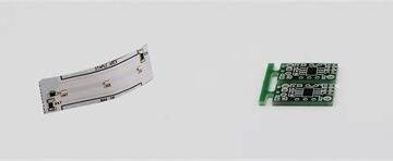
What is a PCB Stackup?
A PCB (Printed Circuit Board) stackup refers to the arrangement of copper layers and insulating materials that make up a printed circuit board. It is a critical aspect of PCB design, as it determines the board’s electrical properties, signal integrity, and manufacturability. A well-designed stackup ensures that the PCB functions as intended and meets the required specifications.
Key Components of a PCB Stackup
- Copper Layers:
- These are the conductive layers that carry electrical signals and power throughout the PCB.
-
The number of copper layers varies depending on the complexity of the design and the required functionality.
-
Insulating Materials:
- Insulating materials, such as FR-4 (Flame Retardant-4), are used to separate and support the copper layers.
-
They provide electrical insulation and mechanical stability to the PCB.
-
Solder Mask:
- A solder mask is a protective layer applied to the outer copper layers of the PCB.
-
It prevents accidental short circuits during the soldering process and protects the copper traces from oxidation and contamination.
- Silkscreen is a printed layer on top of the solder mask that provides text, logos, and component outlines for easy identification and assembly.
Understanding a 3 Layer PCB Stackup
A 3 layer PCB consists of three copper layers separated by insulating materials. This configuration offers a balance between cost and performance, making it suitable for a wide range of applications. Let’s explore the typical stackup of a 3 layer PCB.
3 Layer PCB Stackup Diagram
| Layer | Material | Thickness (mm) |
|---|---|---|
| Top Copper | Copper | 0.035 |
| Prepreg | FR-4 | 0.2 |
| Inner Copper | Copper | 0.035 |
| Core | FR-4 | 0.2 |
| Bottom Copper | Copper | 0.035 |
| Solder Mask (Top) | Epoxy | 0.025 |
| Solder Mask (Bottom) | Epoxy | 0.025 |
| Silkscreen (Top) | Epoxy Ink | 0.015 |
| Silkscreen (Bottom) | Epoxy Ink | 0.015 |
Layers in Detail
- Top Copper Layer:
- This is the outermost layer on the top side of the PCB.
- It typically contains components, signal traces, and power planes.
-
The top copper layer is usually designated as the “component side” of the PCB.
-
Prepreg Layer:
- Prepreg (pre-impregnated) is a partially cured insulating material, typically FR-4, that separates the top copper layer from the inner copper layer.
-
It provides insulation and bonding between the layers during the lamination process.
-
Inner Copper Layer:
- The inner copper layer is sandwiched between the prepreg and core layers.
- It can be used for additional signal routing, power distribution, or as a ground plane.
-
Having an inner layer allows for more complex routing and better signal integrity compared to a 2 layer PCB.
-
Core Layer:
- The core layer is a fully cured FR-4 material that provides the main structural support for the PCB.
-
It separates the inner copper layer from the bottom copper layer.
-
Bottom Copper Layer:
- The bottom copper layer is the outermost layer on the bottom side of the PCB.
- It is often used for additional signal routing, ground planes, or component placement.
-
The bottom layer is sometimes referred to as the “solder side” of the PCB.
-
Solder Mask Layers:
- Solder mask layers are applied to both the top and bottom copper layers.
- They protect the copper traces from oxidation, prevent solder bridging, and provide insulation.
-
Solder mask is typically green in color but can also be found in other colors such as red, blue, or black.
-
Silkscreen Layers:
- Silkscreen layers are printed on top of the solder mask layers on both sides of the PCB.
- They contain text, logos, and component outlines for easy identification and assembly.
- Silkscreen is usually white but can also be found in other colors for better visibility or aesthetics.
Advantages of a 3 Layer PCB
- Increased Routing Density:
- The additional inner copper layer allows for more complex routing compared to a 2 layer PCB.
-
It enables designers to route more signals in a smaller area, resulting in a more compact PCB design.
-
Improved Signal Integrity:
- The inner layer can be used as a ground plane or power plane, which helps to reduce electromagnetic interference (EMI) and improve signal integrity.
-
By separating signals from power and ground, the risk of crosstalk and noise is minimized.
-
Better Power Distribution:
- The inner layer can be used for power distribution, providing a low-impedance path for power delivery to components.
-
This helps to reduce voltage drops and ensure stable power supply to all parts of the PCB.
-
Enhanced Mechanical Strength:
- The additional prepreg and core layers in a 3 layer PCB provide extra mechanical strength and rigidity compared to a 2 layer PCB.
-
This makes the PCB more durable and less susceptible to warping or bending during manufacturing and handling.
-
Cost-Effective:
- While a 3 layer PCB is more expensive than a 2 layer PCB, it is still a cost-effective solution for many applications.
- It offers a good balance between performance and cost, making it suitable for mid-complexity designs.

Designing a 3 Layer PCB Stackup
When designing a 3 layer PCB stackup, several factors need to be considered to ensure optimal performance and manufacturability. Here are some key considerations:
- Material Selection:
- Choose the appropriate insulating material (e.g., FR-4) based on the desired electrical and mechanical properties.
-
Consider the dielectric constant, loss tangent, and thermal expansion coefficient of the material.
-
Copper Thickness:
- Select the appropriate copper thickness for each layer based on the current carrying requirements and signal integrity considerations.
-
Thicker copper layers are better for high-current applications, while thinner layers are suitable for high-speed signals.
-
Layer Arrangement:
- Decide on the arrangement of copper layers and their respective functions (signal, power, or ground).
-
Consider the placement of components and the routing of signals to minimize the length and complexity of traces.
-
Impedance Control:
- If the design requires controlled impedance for high-speed signals, calculate the necessary trace width and spacing based on the stackup and material properties.
-
Use appropriate design tools and calculators to ensure the desired impedance is achieved.
-
Via Placement:
- Plan the placement of vias to interconnect the layers and provide efficient signal routing.
-
Consider the via size, drill diameter, and pad size to ensure manufacturability and signal integrity.
-
Design Rule Check (DRC):
- Perform a thorough DRC to verify that the design meets the manufacturing constraints and design guidelines.
- Check for minimum trace width, spacing, drill size, and other relevant parameters to avoid manufacturing issues.
Manufacturing a 3 Layer PCB
Once the design is finalized and verified, the next step is to manufacture the 3 layer PCB. The manufacturing process involves several stages:
- Inner Layer Fabrication:
- The inner copper layer is patterned and etched according to the design.
- A photoresist coating is applied, exposed, and developed to create the desired pattern.
-
The unwanted copper is etched away, leaving the desired traces and pads.
-
Lamination:
- The patterned inner layer is sandwiched between the prepreg and core layers.
-
The stack is subjected to high temperature and pressure in a lamination press to bond the layers together.
-
Drilling:
- Holes are drilled through the laminated stack to create vias and component mounting holes.
-
The drilling process is precisely controlled to ensure accurate hole placement and size.
-
Plating:
- The drilled holes are plated with copper to create electrical connections between the layers.
-
A copper seed layer is deposited, followed by electroplating to build up the desired thickness.
-
Outer Layer Patterning:
- The outer copper layers (top and bottom) are patterned and etched in a similar manner to the inner layer.
- The photoresist coating is applied, exposed, and developed to create the desired pattern.
-
The unwanted copper is etched away, leaving the desired traces and pads.
-
Solder Mask Application:
- The solder mask is applied to the outer layers and cured to protect the copper traces and pads.
-
Openings are left in the solder mask for component pads and exposed copper areas.
-
Silkscreen Printing:
- The silkscreen layers are printed on top of the solder mask to provide text, logos, and component outlines.
-
The silkscreen ink is cured to ensure durability and legibility.
-
Surface Finish:
- A surface finish, such as HASL (Hot Air Solder Leveling) or ENIG (Electroless Nickel Immersion Gold), is applied to the exposed copper areas.
-
The surface finish protects the copper from oxidation and enhances the solderability of the pads.
-
Electrical Testing:
- The manufactured PCBs undergo electrical testing to verify their functionality and conformance to the design specifications.
- Tests such as continuity, insulation resistance, and high-potential (hipot) testing are performed to ensure the quality and reliability of the PCBs.
Frequently Asked Questions (FAQ)
-
Q: What is the typical thickness of a 3 layer PCB?
A: The typical thickness of a 3 layer PCB ranges from 1.0mm to 1.6mm, depending on the copper thickness and the thickness of the insulating materials used. -
Q: Can a 3 layer PCB have different copper thicknesses for each layer?
A: Yes, it is possible to have different copper thicknesses for each layer in a 3 layer PCB. This allows for optimizing the design based on the specific requirements of each layer, such as current carrying capacity or signal integrity. -
Q: What are the benefits of using a 3 layer PCB compared to a 2 layer PCB?
A: A 3 layer PCB offers several benefits over a 2 layer PCB, including increased routing density, improved signal integrity, better power distribution, and enhanced mechanical strength. It provides more design flexibility and is suitable for mid-complexity designs. -
Q: How does the inner layer in a 3 layer PCB affect signal integrity?
A: The inner layer in a 3 layer PCB can be used as a ground plane or power plane, which helps to reduce electromagnetic interference (EMI) and improve signal integrity. By separating signals from power and ground, the risk of crosstalk and noise is minimized, resulting in cleaner and more stable signals. -
Q: Can a 3 layer PCB be used for high-speed designs?
A: Yes, a 3 layer PCB can be used for high-speed designs with appropriate design considerations. By using controlled impedance traces, careful layer arrangement, and proper signal routing, a 3 layer PCB can support high-speed signals while maintaining signal integrity. However, for very high-speed designs, a 4 layer or higher stackup may be preferred.
Conclusion
A 3 layer PCB stackup is a versatile and cost-effective solution for many electronics applications. It offers a balance between performance and cost, providing increased routing density, improved signal integrity, better power distribution, and enhanced mechanical strength compared to a 2 layer PCB.
When designing a 3 layer PCB, careful consideration should be given to material selection, copper thickness, layer arrangement, impedance control, via placement, and design rule checks. Following best practices and adhering to manufacturing constraints ensures a robust and reliable PCB design.
The manufacturing process of a 3 layer PCB involves several stages, including inner layer fabrication, lamination, drilling, plating, outer layer patterning, solder mask application, silkscreen printing, surface finish, and electrical testing. Each stage plays a crucial role in producing high-quality PCBs that meet the specified requirements.
By understanding the stackup, design considerations, and manufacturing process of a 3 layer PCB, designers and engineers can create optimized and reliable electronic products. Whether it’s for consumer electronics, industrial applications, or medical devices, a well-designed 3 layer PCB can provide the necessary functionality and performance in a compact and cost-effective package.


0 Comments