Surface mount technology (SMT) is a method of producing electronic circuits in which components are mounted directly onto the surface of printed circuit boards (PCBs). SMT has largely replaced the older through-hole technology and has enabled further miniaturization and automation of electronics assembly.
The SMT manufacturing process consists of several key steps:
SMT Component Preparation
SMT components come in standardized packaging formats to facilitate automated assembly. Common types include:
- Chip components – bare silicon dies or discrete components encased in plastic or ceramic. Examples are resistors, capacitors, diodes.
- Flat packs – low profile, rectangular plastic or ceramic packages with leads on 2 or 4 sides. Common for integrated circuits.
- Quad flat packs (QFP) – square packages with leads on all 4 sides, allowing high lead counts.
- Ball grid arrays (BGA) – package with leads in a grid on the bottom, allowing very high lead counts.
Table 1: Common SMT Component Packages
| Package | Description | Lead Count | Image |
|---|---|---|---|
| Chip | Bare die or discrete component | 2-4 | Show Image |
| Flat pack | Rectangular, low profile | 8-28 | Show Image |
| QFP | Square, leads on 4 sides | 32-256 | Show Image |
| BGA | Leads in grid array on bottom | 100-1500 | Show Image |
SMT components go through the following preparation steps:
- Tape and reel packaging – Chips are placed in pockets embossed in plastic carrier tape and sealed with a cover tape. The tapes are wound on reels for loading onto SMT pick-and-place machines.
- Moisture sensitivity precautions – Some components are prone to damage from moisture absorption. These are baked and stored in dry packs with desiccants.
- Solder paste application – Solder paste is applied to PCB pads where components will be placed. This provides the solder to make the joint during reflow soldering.
SMT PCB Design and Fabrication
PCBs for SMT require tighter tolerances and smaller pad/trace sizes than through-hole boards. Key design elements include:
- Smaller pad sizes optimized for chip components.
- Fine line widths and spacing to route traces.
- Smaller vias.
- Tighter control of hole sizes and locations.
- Soldermasks and silkscreens to protect traces and mark locations.
After design, PCB panelization maximizes board area per fabrication panel. Boards are then fabricated with standard processes like photolithography, etching, hole drilling, and plating.
SMT Assembly
SMT assembly is an automated, high precision process with three main steps:
SMT Component Placement
SMT pick-and-place machines automatically populate boards with components from tape reels at very high speeds and accuracy. Key capabilities:
- High speed, multi-nozzle heads pick components and place them precisely.
- Optical alignment systems correct for any PCB/component misalignment.
- Feeders or trays supply components like IC chips, resistors, capacitors.
- Programmable control automates changing components.
SMT Soldering
There are two main SMT soldering techniques:
- Reflow soldering – Entire board is passed through an oven with a temperature profile that melts solder paste deposits. The profile ensures good wetting and joint formation. Nitrogen atmosphere prevents oxidation.
- Selective soldering – Focused heating locally melts solder only on joints to be soldered. Hot bar, laser, induction, or jet spray methods are used. Allows rework of specific joints.
Table 2: SMT Soldering Methods
| Method | How it Works | Advantages | Disadvantages |
|---|---|---|---|
| Reflow | Oven heats entire board according to thermal profile | Fast process of whole board at once | Limited for rework or repair |
| Hot bar | Heated metal bar contacts joints | Lower cost, simple | Slow, potential for thermal damage |
| Laser | Focused laser beam heats joints | Precise, non-contact | Expensive equipment |
| Induction | High-freq magnetic field induces heating | Contactless, fast, clean | Requires susceptors, less flexible |
| Jet spray | Solder spray aimed at joints | Fast, selective | Potential for shorts, mask needed |
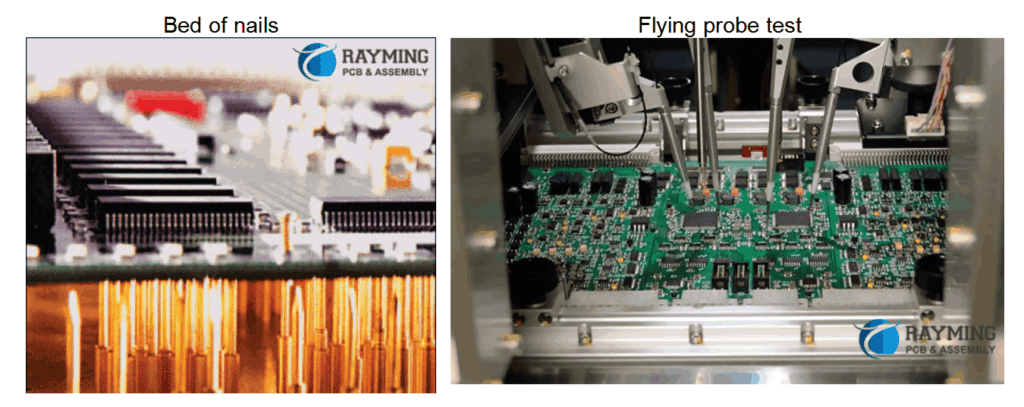
Inspection and Testing
Automated optical inspection (AOI) systems use cameras to check for defects like missing or misaligned components. Electrical tests validate function prior to any protective conformal coating.
SMT Rework and Repair
Despite quality control measures, some SMT assemblies will require reworking defective solder joints or replacing faulty components discovered during testing. This is done manually under a microscope or with special tools.
- Soldering iron – Fine tip can be used to melt and reflow specific joints.
- Solder wick – Braided copper wire removes excess solder for rework.
- Hot air tool – Focused, temperature-controlled air stream for component removal.
- Pick-and-place – Small benchtop versions allow component replacement.
Advantages of SMT
SMT offers many benefits over earlier through-hole PCB assembly:
- Smaller components and closer spacing increase PCB density.
- Automated assembly reduces manufacturing costs.
- Components mount on one side only, enabling double-sided boards.
- Reflow soldering improves joint quality and reliability.
- Reworkability of defective joints or components.
- Standardization enables high-mix, low-volume production.
With increasing miniaturization and cost-reduction pressures, SMT will continue seeing widespread usage in electronics manufacturing.
FAQ
What are the main SMT component types?
The most common SMT component packages are chip components, flat packs, quad flat packs (QFP), and ball grid arrays (BGA). These standard shapes and lead configurations allow automated assembly.
How does reflow soldering work?
In reflow soldering, the entire circuit board assembly passes through a convection oven with a programmed thermal profile. This profile ensures the solder paste melts completely to form reliable joints and then cools gradually to prevent damage.
What is AOI inspection?
Automated optical inspection (AOI) uses cameras and image analysis software to inspect assembled boards. It checks for missing, misaligned, or improperly soldered components and other defects. This improves quality control.
Why can’t through-hole components be used in SMT?
The leads on through-hole components are too large to fit through the vias used in SMT boards. Also, the spacing between SMT component pads is much smaller than through-hole component spacing.
What methods allow reworking SMT joints?
Soldering irons, solder wick, hot air tools, and miniature pick-and-place machines are commonly used to rework SMT solder joints and replace defective surface mount components. Reworkability is a key advantage of SMT.


0 Comments