Printed circuit board (PCB) design and manufacturing relies extensively on computer-aided design (CAD) files specifying physical board geometry, connectivity, documentation, and fabrication instructions needed to produce functional boards. With numerous software tools used across design, engineering, manufacturing, assembly, and testing workflows, understanding the file formats involved facilitates efficiency and quality.
This article explains the key files generated and shared across PCB development toolchains. We cover widely used CAD file extensions and formats, distinguishing source files from manufacturing outputs. Topics include format objectives, typical contents, reasons for different file types, considerations around proprietary encodings versus open standards, version control conventions, and additional usage context. An FAQ addresses common file-related questions.
Gaining familiarity with themed file groupings around PCB data aids designers and engineers in reliably directing critical artwork, fabrication, assembly, and test information across organizational boundaries – smoothly flowing from design conception through volume production.
Common PCB File Types and Extensions
Below are the most prevalent file extensions and formats associated with PCB design and manufacturing stages:
| File Type | Description | Contents |
|---|---|---|
| Native Project/Source Files | Proprietary PCB editor documents fully capturing board specifications together with custom settings in native formats. Facilitates editing. | Full design data, connectivity, dimensions, fabrication settings, user preferences. |
| Manufacturing Output Files | Standard industry formats for fabrication. Contains layered 2D images, drilling files, netlists, etc. | Layer plots, drill positions, net connectivity lists, BOMs, assembly drawings. |
| Gerber Files | *.GBR | 2D vector photoplot images per layer for photo fabrication steps. |
| Drill Files | *.TXT, *.EXL, *.DRR | Numerical control drill files specifying hole sizes and XY drill targets. |
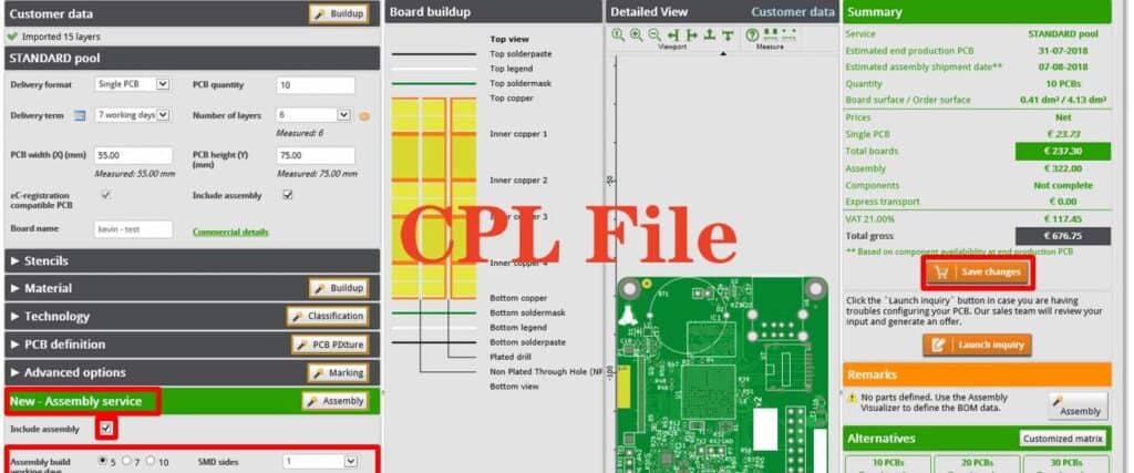
| Bill of Materials Files | *.CSV, *.XLS, *.MDB | Listing of components, refs, values required for assembly. |
| IPC Netlist Files | *.NET | Connectivity graph of pins mapped to components in IPC-D-356A SDX format. |
| ODB++ Files | *.ODB | Manufacturer archived zip containing all intelligent PCB data in standardized format. |
| PDF Files | Print-ready engineering drawings, fabrication documentation. |
Table 1: Common PCB File Extension Types and Descriptions
These represent the primary file groupings passed between senders and receivers across the ecosystem from design teams through manufacturing and test. We next explore the objectives behind different formats.
H2 Tag with Keywords
H3 Tag with Keywords
H4 Tag with Keywords
Purposes of Different File Category Types
PCB file variants serve distinct exchange requirements through workflow phases:
Native Project Files – Proprietary file types allow engineers to completely save, modify, and restore PCB designs locally including custom settings unique to an EDA tool provider. This fully retains development state.
Manufacturing Outputs – To fabricate boards, assembly-focused standardized file types isolate essential physical information required for production. These derive from native projects through export translation.
Exchange Formats – To exchange PCB data upstream or downstream across teams using different EDA toolchains, standardized formats like ODB++ encapsulate complete board data portably avoiding native tool dependency.
Release Packages – Finally, manufacturing drawing PDFs, assembly schematics, BOMs, test procedures, and other documentation collate as comprehensive manufacturing packages released under revision control protocols.
Maintaining versions of both native and export formats facilitates local editing flexibility paired with external production handoff efficiency through compatible dataset standards covering requisite fabrication, assembly, or test detail levels. We next explore typical file contents.
Information Contained Within Major PCB Filetypes
At a high level, PCB files organize into these broad categories by type of data specified:
| File Types | Typical Contents |
|---|---|
| Native Project Files | Full intelligent PCB design data, editing history, user local settings, workspace environment preferences. |
| Manufacturing Outputs | 2D fabrication photoplots by layer, netlists, drill files, bare board documentation drawings. |
| Exchange Formats | Intelligent PCB model combining physical, electrical, documentation, design, fab, assembly, metadata. |
| Release Packages | Manufacturing, validation, verification documentation collated as a comprehensive product dataset for production. |
Table 2: Information Grouped by Output File Types
Deeper comparisons of specific file contents appear under the Format Details sections later this article. With the landscape of file categories understood, we can now compare proprietary encodings against open standards.
Proprietary Tool Formats vs. Open Standards
PCB file storage approaches either rely on:
Proprietary Encodings – Native vector formats efficiently storing complete board data models using closed, compressed or encrypted schemas tying designs to specific editors from vendors like Altium or Cadence.
Open Standards – Non-proprietary interchange specifications like DXF, Gerber or IPC-2581 leverage unified, uncompressed plain-text representations for broader sharing, archiving, and backwards/forwards compatibility.
Each approach carries advantages and disadvantages:
| Proprietary Formats | Open Standards |
|---|---|
| <li>Efficient complete design data compression</li><li>Tight tool integration mechanics</li><li>Encrypted IP protection options</li> | <li>Accessible data portability</li><li>Longevity format support</li><li>Transferability between different tool vendor users</li> |
| <li>Limited forward revision compatibility</li> <li>Vendor tool dependency lock-in</li> | <li>Performance overhead of text-based parsing</li> <li>Often lose intelligent design intent</li> |
Table 3. Relative File Format Comparison Factors
With distinct strengths suiting different exchange objectives, workflows utilize both formats across the development lifecycle – proprietary for efficient editing and standards for distribution.
PCB File Version Control Conventions
Given numerous toolstamps and file outputs involved passing a PCB design through fabrication, assembly then test means keeping shared file versions aligned requires rigor:
Revision Schemes – Encode incrementing revision numbers into file names matching to release documentation. This provides visual traceability.
Archives – Backup snapshot release package aggregates before overwritten to enable recovery from release corruption and retrieval if prior builds require diagnosis.
Change Notes – Detail file changes between revision baselines via appended deltas summary sheets. This focuses manufacturing reviews to modified aspects.
Checksum Integrity – Compute difference checksums on file contents between versions to reveal transmission errors escaping visual inspections.
Apply standardized conventions managing file revision lineage, physically separate distributions from masters, backup comprehensively before overwriting, record deltas explicitly, and validate check digits to assure manufacturing recipients that PCB dataset changes match intended engineering version releases. With file handling best practices covered, we survey typical handoff points.
Hierarchy of PCB Data File Handoffs
Combining various specialized file types allows methodically transitioning mission critical PCB design, fab, assembly, and test detail information across organizational exchange boundaries:
| Source | Receiver | Description |
|---|---|---|
| Design Engineering | Prototype Fabrication | <li>Initial manufacturing testing output files like Gerbers, netlists, drill data.</li> <li>Limited drawings set for first article review.</li> |
| Design Engineering | Product Engineering | <li>Partial native project data to enable manufacturing engineering embellishments.</li> <li>Incorporates assembly fixtures, test points, fixtures.</li> |
| Product Engineering | Outsource Fabrication | <li>Comprehensive manufacturing package with fully updated drawings set.</li> <li>Maximum fabrication yield at volume.</li> |
| Fabrication | Quality Engineering | <li>First article board images for verification sign-off.</li> <li>Quality updated manufacturing package.</li> |
| Fabrication/Quality | Assembly Partners | <li>Fabrication drawing package for assembly methods.</li> <li>Bill of materials, XY placement picks.</li> |
Table 4. Typical Handoff Points Between Functional Organizations
Cascading specialized but interdependent PCB file role responsibility from inception through volume manufacturing underlies smooth transfers ensuring continuity of vital fabrication, assembly, or testing information across teams often spanning continents.
Key File Roles Supporting Manufacturing
Examining typical manufacturing processes reveals how specific PCB file deliverable types enable physical board realization:
| Manufacturing Activity | File Dependency |
|---|---|
| Sourcing Laminates | Stackup diagram PDF drawings |
| Loading NC Machines | Excellon drill files |
| Copper and Mask Layers | Extended Gerber photoplots |
| Gold Finger Plating | Controlled depth routing Gerber |
| Solder Paste Stencils | Gerber paste layers |
| Pick and Place Assembly | Centroid XY coordinate Excel outputs |
| Testing / Inspection | IPC-D-356 Netlist connectivity tests |
Table 5. How Manufacturers Utilize PCB File Outputs
This illustrates the breadth of fabrication, assembly, and test processes relying upon data viewports purpose-built from master native project files and tightly scoped for each stage in a board’s physical realization.
H2 Tag with Keywords
Format Details: Native CAD Project Files
Retaining the editable design source allows modifying, improving, and repurposing PCB layouts as requirements evolve across product generations. Native files preserve complete board data models in proprietary formats saving all intelligence, features, and customizations available for a given EDA tool.
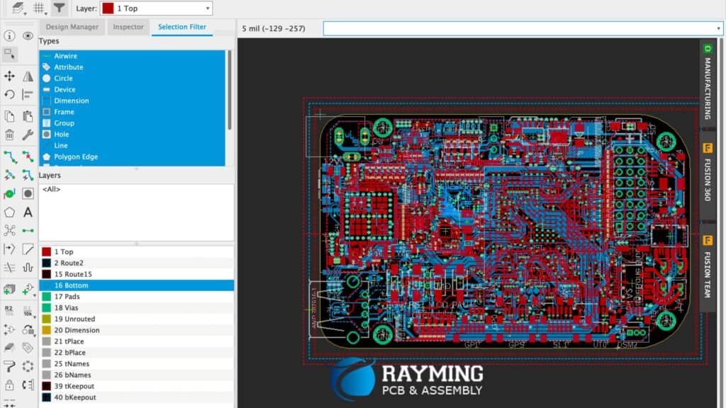
Contents – Fully detailed PCB artwork including routing, signal layers, plane geometries, pad stacks, documentation images, design rule constraints, technology stackup, unused alternate geometries, library source links, preferences, process methodology rules in environment-dependent format.
Tools Generating – printed circuit board editors vendor software like Altium Designer, Cadence Allegro and OrCAD, Mentor Xpedition, and Zuken CR-5000 tool suites.
Recent Version Support – While forward migration compatibility improves with updated export utilities bridging legacy data models, often native tool project files remain constrained to the original creation tool version without intermediate upgrades.
As engineering source data sets, limiting native file external distribution avoids inappropriate modifications corrupting organizational release processes. We next detail manufacturing outputs.
Manufacturing Output File Formats
To physically fabricate boards, a subset of data releases containing only photoplot layers, drilling instructions, connectivity graphs, and supportive documentation drawings:
Contents – Layer-specific board fabrication and assembly artwork photoplots, bare board netlist connectivity, component type and placement pick-lists, Annular ring dimensions, multilayer registration targets, final finish goldmask extents, legend bars detailing fabrication callouts, and numerous industry-standard HE manufacturing outputs.
Tools Generating – Printed circuit layout editors contain export wizards packaging manufacturing output datasets including bare board fabrication layer plots, assembly population instructions for pick and place programming, coordinated hole drilling NC code, and both electrical and visual netlists conveying network connectivity models.
Recent Version Support – Manufacturing exports adhere to slowly evolving formal standards like Gerber RS-274X and IPC-D-356 ensuring forward compatibility across fabrication receiving equipment even as source editor tools incrementally advance.
Releasing production design dataset snapshots allows smoothly transferring board fabrication and assembly details through standardized flows to many industry recipients while avoiding native tool version entanglements.
Exchange Format File Standards
To transfer PCB data between different design environments and organizational archives, standardized exchange specifications retain key design details portably:
Contents – Complete routable connectivity graphs, parameterized pad geometries, component identities and properties, network attributes like impedance characteristics, flexible metadata attachments for fabrication instructions, layer stack sequences, design rules constraints, and optional embedded documentation images supplement core representation.
Tools Generating – Printed circuit layout editors directly output portable exchange formats, or intermediate export converter tools targeting ODB++ transform native projects into multi-vendor compatible transfer syntaxes while retaining core data model intelligence.
Recent Version Support – Actively maintained exchange formats like IPC-2581 integrate updated XML schemas retaining forward revision compatibility as source PCB editor tools incrementally advance across generations to avoid obsolescence.
While retaining more intelligence details than manufacturing outputs yet avoiding proprietary source linkages, portable exchange formats fill an important mid-stage archival role collecting releases across positions in full product lifecycle flows.
H2 Tag with Keywords
Release Package Documentation
Collating manufacturing, validation, and verification documentation together with other supplementary materials produces comprehensive product support dossiers:
Contents – Manufacturing drawings detailing fabrication stackup, layer callouts, panelization arrangements, legend bars, and visual notes are combined with externally facing product assurance documentation like warranty cards, user manuals, and quick start guides extending beyond strictly PCB fabrication datasets alone when bundled as turnkey release packages.
Tools Generating – Printed circuit layout editors, external computer-aided publishing software, document bundle utilities, optical character recognition, and manual organization arranges multimedia reference content spanning embedded PCB visuals through post-production collateral into cohesive product support libraries ported over web interfaces.
Recent Version Support – Release package content structure changes slower than core layout file representations, allowing these broad collections longer useful viability across generations once initially compiled, with document subset deltas updated incrementally on manufacturing revision cycles.
Well-maintained product baseline documentation gives recipients immediate contextual orientation when accessing new or updated PCB design data handoffs during development or sustaining manufacturing stages.
FAQ
What files should accompany new PCB fabrication and assembly orders?
Typical manufacturing transmittals encompass layered board fabrication artwork Gerber files, precision numerical control drill files, pick-and-place centroid list, bill of materials, well-annotated drawings with stackup and legend bars, and electrical netlists conveying component pin connectivity.
What key details distinguish dependable file revision releases?
Reliable PCB dataset revision packages encapsulate fully quantified version designators within filenames, ideally reference a configuration-managed change summary sheet enumerating incremental deltas, contain integral file checksums validating perfect delivery transfers, bundle into a dated archive record, and store separately from engineers’ active working stores.
Could manufacturing process if source native files disappeared?
Absent master source database recovery prospects once fabrication datasets received and secondary documentation libraries maintained, manufacturers can likely sustain production relying on latest successfully validated output snapshot deliveries fortunately stored redundantly at multiple production line stations, albeit foregoing incremental engineering change order improvements until substituting re-generated fabrication file updates.
What risks arise specifying fabrication files in proprietary formats?
Tying manufacturing site equipment to rare and slowly fading legacy software environments needed parsing a proprietary artwork photoplot format risks production halts when eventually encountering aged software failures, forced operating system upgrades severing compatibility, exhausted license key allocations, or discontinued vendor tool support options – whereas human-readable ASCII formats sustain backwards longevity.
Why retain outdated PCB revisions even after new versions release?
Storing prior revision design snapshots protects valuable production diagnostics insight when root causing subsequent faults or anomalies against known good assemblies after attempting process improvements, enables direct dataset comparisons quantifying filed changes more accurately through file differencing, and allows reconstituting authoritative manufacturing configuration should unintentional alterations corrupt purported newer active data stores.
Conclusion
In summary, printed circuit layout data flows through numerous file manifestation sharply focused on facilitating either incremental improvements when retained in native editable forms circulation confined internally amongst engineers, or achieving physical fabrication build objectives when exported to external production partners via strictly standardized interchange file formats discarding non-essential decoration once essential physical target characteristics crystallize. Learning to identify, manage, exchange, and apply appropriate role-specific PCB data file containers smooths development and assures manufactured outcomes match tightly bounded digital specifications originating across design, engineering, and manufacturing planning toolchains.


0 Comments