Streamlining PCB Production for Faster Time-to-Market
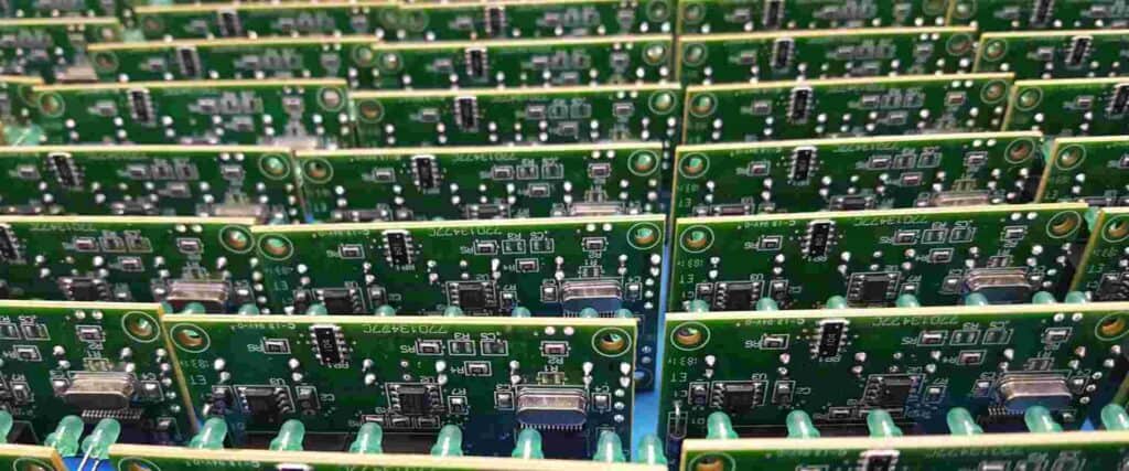
The ability to quickly assemble printed circuit boards (PCBs) is critical for companies looking to accelerate time-to-market for new products. Fast turn PCB assembly enables engineers to rapidly prototype designs, verify functionality, and get products to customers faster. This article explores strategies and techniques for expediting PCB assembly without sacrificing quality or driving up costs prohibitively.
Understanding the PCB Assembly Process
PCB assembly consists of soldering electronic components onto a printed circuit board. The assembly process typically involves three key steps:
The bare PCB is fabricated based on the design files. The board has copper tracks to route signals and solder mask to protect copper from oxidation.
Stencil Fabrication
A metal stencil is created with cutouts matching the solder pads on the PCB. The stencil is used to apply solder paste precisely to the PCB during assembly.
Component Placement and Soldering
Components are accurately placed on the PCB and the board passes through a reflow oven to melt the solder paste, adhering components to the pads.
Strategies for Fast Turn PCB Assembly
Here are some proven techniques to accelerate PCB assembly turnaround times:
1. Use an Experienced Manufacturer
Partnering with an assembly provider that specializes in fast turn production is crucial. They have streamlined processes, supply chain expertise, and resources to deliver quality boards quickly.
2. Provide Complete Design Data Upfront
To avoid delays, supply complete Gerber files, bill of materials, assembly drawings, and other documentation in the native CAD file format. Thorough data enables rapid design review and tooling prep.
3. Use Standard Components
Standard components are easier to source quickly than custom or rare parts. Avoid hard-to-find parts when possible. Provide component manufacturer part numbers for best results.
4. Eliminate Connectors
Soldered connections are faster than mechanical connectors like headers or edge card connectors. Avoid connectors to simplify and speed assembly.
5. Utilize Design for Manufacturing (DFM) Principles
Optimizing the PCB layout and component selection for manufacturability reduces assembly issues and prevents delays for re-design. Consult a DFM expert early in the design process.
6. Perform Test Builds
Do small test builds to validate assembly procedures, determine the optimal solder paste, assess part placement accuracy, and refine programming. This reduces errors when scaling up.
7. Validate Components Before Full Production
Have the manufacturer do an early validation build with a small number of boards to confirm all components are correct and properly sourced before full production. This prevents component problems from surfacing late in the build.
8. Multi-sourcing Components
Work with distributors to source each component from multiple vendors. This provides flexibility to switch vendors if one has supply issues, minimizing procurement delays.
9. Stager Component Supply
Don’t require all components to be available upfront. Allow the manufacturer to start SMT assembly if even 50-80% of components are in stock, staggering delivery of the rest. This avoids delays from long lead time parts.
10. Build in Small Batches
For very fast turnaround, build in small batches of 25-50 boards rather than hundreds at once. This gets working boards to engineers faster for prototyping and testing if timeline is critical.
Managing Trade-Offs
While fast turn assembly is possible, project managers must weigh trade-offs between speed, cost, and capabilities:
- Extremely aggressive lead times will increase costs and limit manufacturing options. Allow some scheduling flexibility when possible.
- Smaller board sizes are typically faster to assemble than larger, more complex designs. Prioritize miniaturization and simplicity.
- Bleeding edge component technologies may have longer lead times. Use proven, widely available component families as able.
- Hand soldering or manual assembly will be slower than automated assembly. Expect to pay a premium for hands-on human craftsmanship.
- Ordering quantities above ~25 units will generally reduce per unit pricing. Balance expedited turnaround with cost savings from larger batches.
- Some advanced technologies like HDI, high density BGAs, embedded passives may restrict assembly options. Seek feasibility feedback before finalizing designs.
Smart trade-offs will minimize total development time without maxing out the budget.
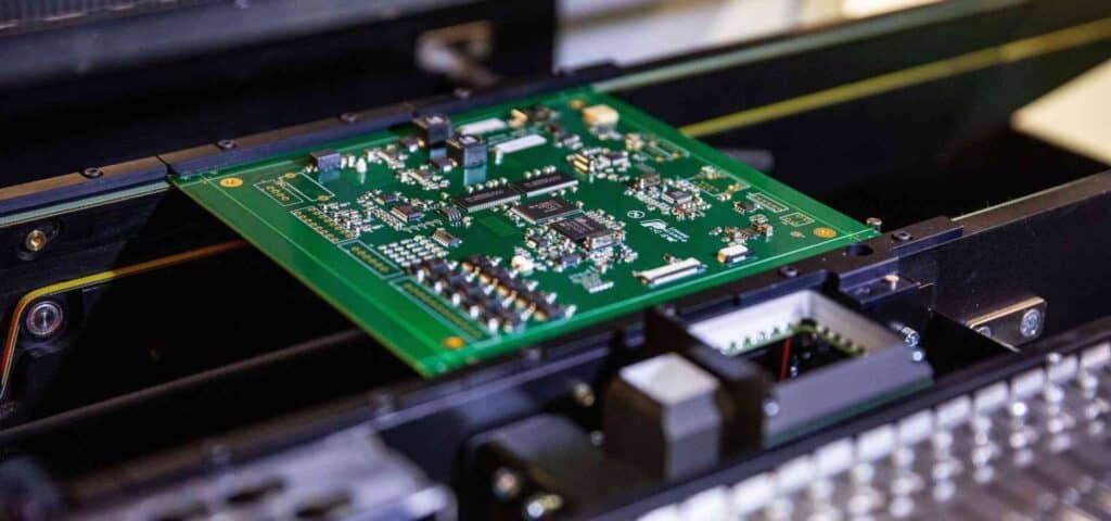
SMT Assembly Process Optimization
For surface mount assembly, production planners can utilize several process refinements to reduce assembly time:
Employ High Speed Chip Shooters
Use the latest high speed SMT pick-and-place equipment to rapidly mount components. Machines with multiple heads and feeders optimize pace.
Minimize SMT Programming
Programmers convert component XY coordinates from CAD into machine code to position parts. Simpler boards require less programming time.
Modularize Programming
Store common groups of parts as modules that can be quickly inserted in programs, shortening programming for repetitive circuits.
Maximize Commonality
Using common footprints, packages, orientation, etc. across the entire BOM simplifies programming and changeovers between boards.
Improve Changeover Efficiency
Streamline changeovers between different board designs by storing feeders and optimizing machine setup procedures.
Tune Solder Paste Deposition
Adjust solder stencil thickness, aperture size, and print speed to deposit just the right amount of paste. This achieves high first pass soldering yields.
Refine Thermal Profiles
Carefully develop custom reflow oven thermal profiles that accurately match the needs of boards and components. This prevents rework from insufficient or excessive reflow.
With an optimized SMT process, assembly providers can quickly and reliably produce high yields of complex boards in 24-48 hours or less.
Example Fast Turn Scenarios
To make these concepts more concrete, below are two examples of fast turn PCB assembly scenarios:
Scenario 1:
A startup needs to build a run of prototype boards ASAP to demo at an upcoming trade show in 3 weeks. They provide gerber files, BOM, and component samples to an experienced assembly provider and request 25 units within 5 business days. To meet the deadline, the provider sources long-lead components in advance while programming and tooling are finalized. They procure enough components for 100 boards to qualify additional suppliers. The programming, stencil, and some components are modularized and stored for quick reuse. By staging supplies and front-loading preparation, the provider delivers 30 prototypes in 4 business days.
Scenario 2:
An R&D team needs to build a few boards the next morning to debug a problem spotted in final system integration. They contact their trusted assembly provider at 5pm with a stripped down version of the design using on-hand components only. After business hours, a dedicated team of technicians and engineers prepare programming and tooling based on the submitted data. They hand-assemble 5 boards with in-house components, completing the build by morning. The early engineering samples enable immediate fault isolation to keep the main project build on-schedule.
Key Takeaways
- For fast PCB assembly turnaround, partner with experienced manufacturers and provide complete design data upfront.
- Standardize on widely available components whenever possible. Eliminate connectors and minimize custom parts.
- Use design principles like modularity and commonality to simplify programming and assembly processes.
- Manage trade-offs between speed, cost sensitivity, design complexity and quality. Allow scheduling flexibility when possible.
- Process optimization techniques like modular programming, rapid changeovers and staged component supply enable rapid ramp up.
- Both manual and automated assembly have roles, depending on project priorities like due date, budget or quantity.
With the right approach, electronics companies can slash PCB assembly lead times to prototype, test and release products faster. Tight collaboration between design and manufacturing teams is the key to fast turn success.
Frequently Asked Questions
What is the typical lead time for fast turn PCB assembly?
For simpler board designs, experienced assemblers can deliver prototypes or small batches within 24-48 hours. More complex boards at higher volumes may require 5-7 days minimum. Expedited lead times under 24 hours are possible but will increase costs significantly.
What design guidelines help enable fast turn assembly?
Some best practices include: standard component sizes/footprints, widely available parts, modular/repetitive design, elimination of connectors, minimizing BOM line items, and compliance with design for manufacturing guidelines.
How large of a production run can be supported with fast turn assembly?
Fast turn is ideal for prototyping and low-mid volume batches under 500 units. For quantities above 1000+, standard lead times are recommended to control costs. Small test builds of 25-50 units can be assembled very rapidly.
What steps do assembly providers take to reduce programming time?
Programming time can be reduced by maximizing component standardization/commonality, reusing programming modules for repetitive assemblies, and employing software tools to speed conversion of pick-and-place data.
How soon should I contact an assembler to start a fast turn project?
Notify assembly partners as early as possible, ideally the moment the design is finalized and gerber files are complete. This provides maximum time for programming, documentation review, part sourcing, and other preparations.


0 Comments