In the world of printed circuit board (PCB) design, flexibility and adaptability are crucial factors for meeting the ever-evolving demands of modern electronics. While traditional rigid PCBs have been the industry standard for decades, the emergence of flex rigid PCBs has opened up new possibilities for innovative designs and applications. This article delves into the concept of flex rigid PCBs, exploring their characteristics, advantages, design considerations, and diverse applications.
Introduction to Flex Rigid PCBs
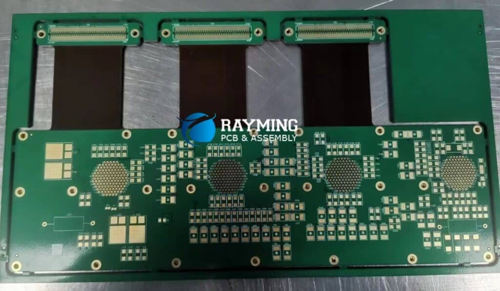
A flex rigid PCB is a unique type of circuit board that combines the properties of both rigid and flexible printed circuits. It consists of rigid sections, typically made of standard FR4 or other rigid laminate materials, seamlessly integrated with flexible sections composed of polyimide or other flexible dielectric materials.
The rigid sections provide mechanical stability and support for mounting components, while the flexible sections allow for bending, folding, or flexing to accommodate specific design requirements or space constraints. This hybrid construction enables a single PCB to adapt to various form factors and geometries, making it an attractive solution for a wide range of applications.
Characteristics and Benefits of Flex Rigid PCBs
Flex rigid PCBs offer several distinct advantages over traditional rigid PCBs or flexible PCBs alone. Here are some key characteristics and benefits:
- Versatility: Flex rigid PCBs can be designed to fit into tight spaces, navigate around obstacles, or conform to unique shapes, providing designers with increased flexibility in their approaches.
- Reduced Interconnections: By integrating rigid and flexible sections into a single PCB, the need for separate interconnections, such as cables or connectors, is significantly reduced, simplifying the overall design and improving reliability.
- Improved Durability: The rigid sections of the PCB provide mechanical support and protection for the components, enhancing overall durability and resistance to shock, vibration, and other environmental factors.
- Space Optimization: The ability to fold or bend the flexible sections allows for efficient use of available space, making flex rigid PCBs ideal for compact and space-constrained applications.
- Reduced Weight: Compared to traditional rigid PCBs with multiple interconnections or cables, flex rigid PCBs can offer a more lightweight solution, which is beneficial in applications where weight is a critical factor, such as aerospace or portable electronics.
- Design Flexibility: The combination of rigid and flexible sections allows for unique design configurations, enabling engineers to create innovative and customized solutions tailored to specific requirements.
Design Considerations for Flex Rigid PCBs
While flex rigid PCBs offer numerous advantages, their design and manufacturing processes require careful consideration of several factors to ensure reliable and high-quality outcomes. Here are some key design considerations:
- Materials Selection: Choosing the appropriate materials for both the rigid and flexible sections is crucial. The rigid sections typically use standard FR4 or other rigid laminate materials, while the flexible sections commonly employ polyimide or other flexible dielectric materials. The material properties, such as thermal expansion coefficients, dielectric constants, and flexibility, must be carefully evaluated.
- Bend Radius and Flex Life: The flexible sections of the PCB are designed to bend or flex, but there are limitations on the minimum bend radius and the number of bend cycles (flex life) that the material can withstand without degradation or failure. These factors must be considered during the design phase to ensure long-term reliability.
- Thermal Management: Heat dissipation can be a challenge in flex rigid PCBs, particularly in the flexible sections where components cannot be mounted directly. Proper thermal management strategies, such as the use of thermal vias, heat sinks, or heat-spreading materials, may be required to prevent overheating and ensure proper operation.
- Interconnections and Transitions: The transition zones between the rigid and flexible sections require careful design considerations to ensure reliable electrical and mechanical connections. Proper via placement, routing techniques, and stress-relief strategies must be employed to minimize the risk of stress concentration and potential failures.
- Manufacturing Processes: The manufacturing processes for flex rigid PCBs are more complex than those for traditional rigid or flexible PCBs. Special techniques, such as selective plating, laser ablation, or adhesive bonding, may be required to create the hybrid structure. Working with experienced and capable manufacturers is essential to ensure high-quality and reliable products.
- Testing and Validation: Due to the unique nature of flex rigid PCBs, comprehensive testing and validation processes are necessary to verify mechanical, electrical, and environmental performance. This may include bend tests, thermal cycling tests, vibration tests, and other specialized testing procedures.
Applications of Flex Rigid PCBs
Flex rigid PCBs have found applications across a wide range of industries and products, thanks to their versatility and unique capabilities. Here are some notable applications:
- Aerospace and Defense: Flex rigid PCBs are widely used in aerospace and defense applications, such as avionics systems, missiles, and satellites, where compact and lightweight designs are essential, and the ability to withstand harsh environments is critical.
- Automotive Electronics: The automotive industry has embraced flex rigid PCBs for applications such as instrument clusters, infotainment systems, and advanced driver assistance systems (ADAS), where the combination of rigid and flexible sections enables innovative designs and efficient space utilization.
- Medical Devices: In the medical field, flex rigid PCBs are employed in a variety of devices, including surgical tools, patient monitoring systems, and implantable devices, taking advantage of their compact size, durability, and adaptability to unique form factors.
- Consumer Electronics: Flex rigid PCBs are found in various consumer electronics products, such as smartphones, laptops, and wearable devices, where they facilitate compact and ergonomic designs while accommodating complex component layouts and interconnections.
- Industrial Automation: The ruggedness and flexibility of flex rigid PCBs make them suitable for industrial automation applications, such as robotics, control systems, and motion control devices, where they must withstand harsh environments and provide reliable operation.
- Telecommunications: In the telecommunications industry, flex rigid PCBs are used in base stations, antennas, and other communication equipment, enabling compact designs and facilitating efficient signal transmission and connectivity.
Table: Comparison of Rigid PCBs, Flexible PCBs, and Flex Rigid PCBs
| Characteristic | Rigid PCBs | Flexible PCBs | Flex Rigid PCBs |
|---|---|---|---|
| Mechanical Stability | High | Low | Combination of rigid and flexible sections |
| Flexibility | No | Yes | Flexible sections can bend or fold |
| Durability | High | Moderate | Rigid sections provide durability, flexible sections may be susceptible to damage |
| Space Optimization | Limited | Good | Excellent, flexible sections can conform to tight spaces |
| Weight | Heavier | Lighter | Lightweight, depending on design |
| Design Flexibility | Limited | Good | Highly flexible, combining rigid and flexible sections |
| Manufacturing Complexity | Low | Moderate | High, specialized processes required |
| Cost | Lower | Higher | Higher, due to complex manufacturing |
Frequently Asked Questions (FAQ)
- What is the difference between a flex rigid PCB and a flexible PCB? A flex rigid PCB combines both rigid and flexible sections in a single PCB, while a flexible PCB is entirely composed of flexible dielectric materials and does not have any rigid sections.
- Can components be mounted on the flexible sections of a flex rigid PCB? While it is possible to mount components on the flexible sections of a flex rigid PCB, it is generally not recommended due to the risk of component damage or failure during bending or flexing. Components are typically mounted on the rigid sections to ensure mechanical stability and reliability.
- What are the typical materials used for the rigid and flexible sections of a flex rigid PCB? The rigid sections of a flex rigid PCB commonly use standard FR4 or other rigid laminate materials, while the flexible sections often employ polyimide or other flexible dielectric materials.
- What factors determine the minimum bend radius and flex life of a flex rigid PCB? The minimum bend radius and flex life are primarily determined by the properties of the flexible dielectric material used, as well as the design of the flex circuit itself, including factors such as copper thickness, dielectric thickness, and the presence of stiffeners or reinforcements.
- How does the manufacturing process for flex rigid PCBs differ from traditional rigid or flexible PCBs? The manufacturing process for flex rigid PCBs is more complex, involving specialized techniques such as selective plating, laser ablation, or adhesive bonding to create the hybrid structure by combining rigid and flexible sections. Additionally, comprehensive testing and validation processes are necessary to ensure mechanical, electrical, and environmental performance.


0 Comments