Ceramic printed circuit boards provide unique performance advantages making them the top choice for niche applications with stringent demands like extreme temperatures, high frequency, low loss, ultra stability and reliability needs.
This guide will cover:
- Ceramic PCB Overview
- Types of Ceramic Boards
- Ceramic Substrate Materials
- Comparison to FR4 Boards
- Ceramic PCB Fabrication
- Applications and Uses
- Pros and Cons
- Cost Considerations
- FAQs
So let’s get started exploring when and why ceramic boards get deployed in electronic designs.
Ceramic PCB Overview
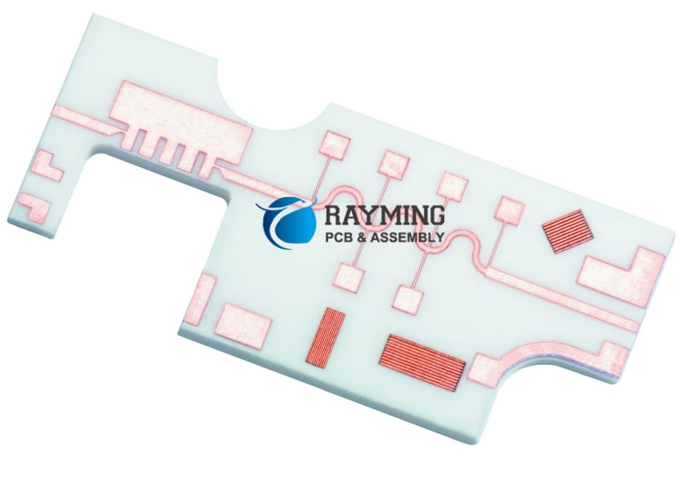
Unlike conventional fiberglass reinforced plastic FR4 boards, ceramic printed circuit boards use ceramic material like aluminum oxide or aluminum nitride as base dielectric substrate instead of woven glass.
Conductor layers – Thin sheets of metallic conductors like copper or tungsten get bonded to the ceramic base. Conductor patterns with traces, pads and vias etched similar to FR4 fabrication process.
Superior dielectric – The ceramic substrate offers far lower electrical losses, extremely consistent performance across temperature range and through frequencies into microwave region when compared to resin based boards.
These stellar electrical characteristics along with ruggedness justify applications requiring uncompromised stability and reliability in demanding operating environments.
Types of Ceramic Boards
There are two prime varieties of ceramic PCBs:
Alumina Boards
- Alumina ceramic – Aluminum oxide – Al2O3 used as substrate
- Very hard and temperature resistant
- Copper metalization offers conductivity
- Lowest cost ceramic material
Applications – RF circuits, aviation electronics, automotive, downhole equipment
Aluminum Nitride Boards
- Aluminum nitride (AlN) ceramic base
- High thermal conductivity for heat dissipation
- Lowes dielectric loss tangent
- Copper, tungsten or molybdenum metallization
Applications – High power RF devices, radars, satellite equipment, medical diagnostics
Next let’s explore popular ceramic substrate materials used.
Ceramic Substrate Materials
Some commonly used substrate ceramics include:
Alumina (Al2O3) – Most widely adopted. High strength and rigidity with excellent electrical insulation capability. Thermally conductive but prone to cracks under thermal shocks.
Aluminum Nitride (AlN) – Top choice for thermal management needs due to heat conductivity. Costlier than alumina. Lower dielectric constant benefits high frequency uses.
Beryllia/Beryllium Oxide (BeO) – Exceptional thermal performance but toxicity restricts widespread adoption. Controlled material requiring special handling.
Zirconia (ZrO2) – Very hard mechanically. Withstands high temperatures and corrosion. Zirconia toughened alumina (ZTA) composite also used.
Silicon Nitride (Si3N4) – Stronger than alumina with higher fracture toughness. Its high temperature capabilities find uses in the aerospace sector.
Compared to mainstream FR4 boards, let’s weigh pros and cons of ceramic PCB technology.
Ceramic Boards vs. FR4 Boards Comparison
| Parameter | Ceramic PCB | FR4 PCB |
|---|---|---|
| Dielectric Constant | <10 | 4.2 to 4.8 |
| Loss Tangent | 0.004 | 0.015 |
| Moisture Absorption | Nil | High – 0.2% |
| Thermal Conductivity | Excellent | Average |
| Thermal Expansion | 3 ppm/C | 12 to 20 ppm/C |
| Dielectric Strength | 200 to 300 V/mil | 50 to 150 V/mil |
| Frequency Range | Up to GHz microwave region | Up to 5 GHz |
| Flexibility | Rigid, brittle boards | Flexible, bendable boards |
| Raw Material Cost | Very expensive | Economical |
| Fabrication Process | Challenging, lower yields | Mature, high yields |
Ceramic PCB’s trump cards of electrical performance stability and ruggedness comes at steep cost premium limiting applicability to mainly high reliability defence, space and scientifically oriented applications.
Now let’s cover some nuances of their fabrication process.
Ceramic PCB Fabrication
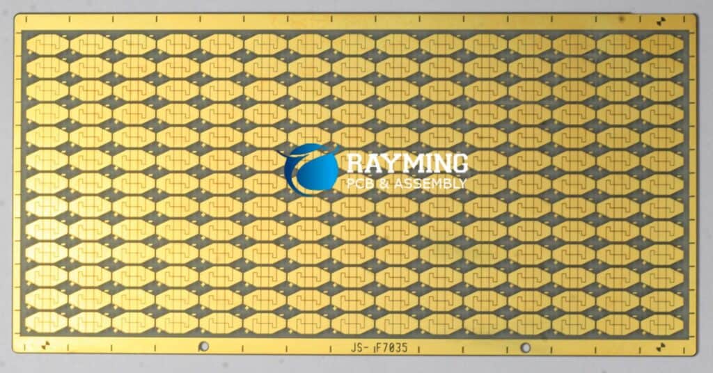
Ceramic board fabrication follows process flow similar to conventional PCBs but with some additional steps making it overall more complex, lower yielding and expensive process:
Conductor Metallization – Molybdenum or tungsten refractory metals offer extended temperature resilience compared to copper traces. Active brazing attaches metallization layer to ceramic plates.
Machining – Post firing, the blank ceramic boards undergo precision CNC machining to achieve target thickness. Costly diamond tooling required due to hardness.
Via Formation – Exotic micro-drilling or laser cutting techniques drill fine holes before undergoing metallization for vertical interconnects between layers.
Insulation Layer – Thin layers of ceramic dielectric paste or dense low porosity ceramic sheets build multilayer boards. Firing permanently fuses insulation layers between metallized films.
Edge Metallization – Plating side edges improves connectivity, grounding and shielding on boards meant for high frequency precision electronics usage.
Testing – Small fabrication flaws get amplified into failures due to ceramic brittleness. So rigorous inspection, microscopy, x-ray and electrical testing needed to validate builds before shipment.
Next let’s cover major applications leveraging merits of ceramic PCB technology.
Applications and Uses
Some key applications benefiting from ceramic printed circuit boards include:
High Frequency & Microwave Circuits
Ultra low loss tangent through microwave band makes ceramic substrates top choice for waveguides, antennas, oscillators and RF amplifiers assuring signal integrity. Alumina, Aluminum nitride and Zirconia boards commonly used.
Example devices – Radars, aviation electronics, missile guidance systems, satellite communication hardware, radio telescopes
High Power Electronics
Aluminum nitride (AlN) ceramic’s high thermal conductivity enables efficient heat sinking from high power density devices preventing detrimental heating ensuring stable reliable functionality.
Example applications – Electric vehicle power systems, renewable energy converters, industrial motor drives, traction control hardware.
High Temperature Electronics
Ceramic boards easily withstand soldering heat alongside sustaining functionality under high temperature deployments without deterioration benefiting underhood automotive electronics and downhole drilling equipment.
Medical Diagnostics
Aluminum nitride’s dimensional stability ensures accuracy of imaging equipment used in medical diagnostics and surgical applications.
Aerospace & Defense
Spacecraft electronics, mission critical aviation electronics place high value on stability and resilience of ceramic PCBs against G forces, intense vibration and extended duration reliability requirements.
Pros and Cons of Ceramic PCBs
Benefits
- Extreme thermal conductivity and consistency
- Ultra low transmission losses through high frequencies
- Structural rigidity and ruggedness
- Hermetic sealing capability
- Radiation and corrosion resistance
Drawbacks
- High procurement costs
- Lower fabrication yields
- Brittle boards prone to cracks
- Restricted mainly to niche applications
For enhancing manufacturability and maximizing product reliability:
Ceramic PCB Design Considerations
- Simplify layout routing to limit thin lines and tight clearances
- Allow for insulation expansion differences versus metallization
- Incorporate expansion slots on larger boards
- Implement compliant interface interconnections to hosts to minimize stresses
- Specify smooth edges to minimize chip outs
- Add generous corner radii to avoid cracks
Ceramic PCB Cost Factors
Given additional fabrication processing steps and constrained market size, procuring ceramic printed circuit boards carries steep cost premiums with order prices often entering thousands of dollars even for modest board sizes.
Key variables impacting ceramic PCB costs:
- Board dimensions & layer counts
- Land pattern densities
- Thermal budgets
- Special handling needs
- Order volumes & lead times
For mission critical programs where performance reigns supreme over product costs, precision ceramic boards deliver unmatched electrical functionality. But stick to conventional PCBs for commercial grade applications to maximize value engineering.
Frequently Asked Questions
Here are some common queries regarding ceramic PCB technology:
Q: Are ceramic PCBs suitable for hobbyist usage?
The high costs and long fabrication lead times make ceramic boards impractical for prototyping, hobbyist or small batch usage. They are tailored for commercial to aerospace and defense grade engineering projects.
Q: Can components be soldered onto ceramic boards?
Attaching miniature surface mount devices or connectors requires specialized solders and thermal profiles to prevent solder leaching or cracks under thermal stresses.
Q: How thick are typical ceramic PCBs?
Alumina boards are commonly fabricated in thickness range of 10 to 30 mils to strengthen their mechanical rigidity and minimize warping while allowing vertical interconnection vias routing. Thinner constructions down to 5 mil also possible but more delicate.
Q: Are there ceramic based “chip” packages for ICs?
Besides ceramic boards replacing conventional PCB substrates, various ceramic compounds and processes also produce hybrid integrated circuit packages and chip carriers used in packaging semiconductors.
Q: What about fabrication of ceramic flexible circuits?
Yes, flexible ceramic PCBs are also manufacturable either through laminating conductive metals like gold, platinum or nickel onto flexible fired green tape ceramic sheets or metalizing thin multilayer cofired ceramic sheets achieving modest degrees of mechanical flexure capacity.
That wraps up a detailed overview of performance orientated ceramic PCB technology contrasted against conventional printed circuit boards. For applications placing a premium on electrical precision stability under challenging high temperature, radiation intense operating environments, consider exploiting the electrical virtues of ceramic substrates early during architectural design phase notwithstanding their premium procurement costs.


0 Comments