Introduction
LED (light emitting diode) lighting has become increasingly popular in recent years due to its energy efficiency, long life span, and design flexibility compared to traditional incandescent and fluorescent lighting. At the heart of any LED light fixture or bulb is the LED circuit board, which houses the LED chips and other electronic components necessary to power and control the LEDs. The design and assembly process for these circuit boards is crucial in determining the performance, reliability, and cost-effectiveness of the finished LED lighting product.
In this article, we will take a closer look at the key steps involved in assembling LED light circuit boards, including SMT (surface mount technology) manufacturing processes, component selection, board layout considerations, quality control and testing. Gaining insight into the assembly process will help design engineers, procurement managers, and manufacturing teams better understand how to optimize circuit board design and production for LED lighting applications.
Overview of the LED Light Circuit Board Assembly Process
The assembly process for an LED light circuit board consists of two main phases:
1. SMT (Surface Mount Technology) Manufacturing
This involves mounting and soldering SMD (surface mount device) components onto the PCB (printed circuit board). Key steps include:
- Solder paste application – solder paste is printed or dispensed onto PCB pads.
- Component placement – SMD components are precisely placed onto board using pick-and-place machines.
- Soldering – The board passes through a reflow oven to melt solder and attach components.
2. Through-Hole Assembly
Larger components like connectors or heat sinks are mounted using through-hole insertion and wave soldering:
- Component insertion – Leads are inserted into plated through-holes in the PCB.
- Wave soldering – Bottom side of board passes over molten solder, sealing leads into board.
Testing, quality checks, protective coatings, and other secondary operations are also carried out before boards are shipped to lighting fixture assemblers.
Key Design and Assembly Considerations
Several important factors need to be considered when designing and assembling LED light circuit boards:
Thermal Management
LEDs generate significant heat that must be dissipated. Thermal design considerations include:
- PCB material – FR-4, metal core PCBs, ceramic substrates better conduct heat.
- Thermal pads/vias – Enable heat transfer from LEDs to board and heat sink.
- Component placement – Optimize layout to avoid hot spots.
- Heatsinking – Use of heat sinks or thermal adhesives to dissipate heat.
Power Integrity
LEDs require stable, clean power to function properly and reliably:
- Power topology – Use of buck, boost, linear regulators or DC/DC converters.
- Decoupling capacitors – Filter noise on power supply lines.
- PCB traces – Properly sized traces handle required current levels.
- Connectors – Rating and quality to handle power levels.
LED Selection and Placement
Key considerations for the LEDs:
- LED package type – SMD or through-hole package.
- Viewing angle, lumen output, color temperature.
- Assembly process – compatible with soldering methods.
- Layout – optimize spacing and grouping for light uniformity.
Driver Components
The LED driver circuitry requires careful selection of components like:
- Microcontrollers – control LED output.
- Transistors, MOSFETs – switch LEDs on/off.
- Resistors, capacitors – shape current and voltage.
- Opto-isolators – isolate low and high voltage sides.
SMT Assembly Process Steps
Here is a more detailed overview of the typical SMT manufacturing process used to assemble LED circuit boards:
1. Solder Paste Printing
The first step is to apply solder paste to the contact pads on the PCB where components will be placed. Solder paste contains tiny spherical solder particles suspended in flux. It can be applied using stencil or screen printing, or jetting methods. The application must be precise and consistent to avoid defects.
2. Pick and Place Assembly
SMD components are precisely placed onto the wet solder paste using automated pick-and-place machines. These machines use vacuum nozzles to pick components from reels and trays, then position them on the board using high precision robotics. Accuracy of 0.05mm or better is needed to ensure reliable solder joints.
3. Reflow Soldering
The circuit board with components goes through a reflow oven to melt the solder paste and attach the components. The board passes under heaters and the temperature follows a carefully controlled profile to activate the solder flux, evaporate solvents, then melt the solder without damaging components. Common reflow methods include convection, vapor phase, and infrared/laser heating.
4. Automated Optical Inspection (AOI)
Once soldered, boards pass under cameras that automatically inspect for defects like missing or misaligned components, insufficient solder, shorts, opens, etc. Any boards with defects can be reworked before moving to the next steps.
5. Conformal Coating
A protective plastic coating is often selectively applied over the assembled boards to prevent damage from moisture, dirt, electrical shorts or corrosion during operation. The coating electrically insulates board and provides environmental and mechanical protection.
6. Programming and Functional Test
For boards with microcontrollers or digital logic, the electronic components are then programmed with firmware that controls their functions. The completed boards are also electrically tested to verify they function as intended before leaving manufacturing.
Through-Hole Assembly Process
While SMT manufacturing attaches the small surface mount components, there are typically some larger through-hole parts like connectors, fuses, heat sinks that need mounting as part of circuit board assembly.
1. Component Insertion
Components with wire leads are inserted into the plated through-holes in the PCB by automatic or manual insertion machines. Correct orientation and seating of leads is checked.
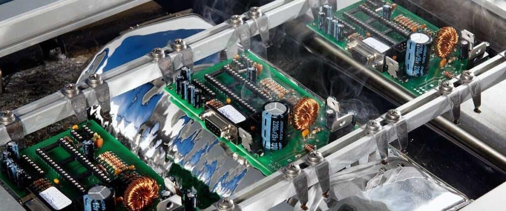
2. Wave Soldering
The assembled boards pass bottom-side down over a flowing wave of molten solder. The solder wets and is drawn up into the through-holes by capillary action, forming reliable solder joints to attach the leads. Nitrogen prevents oxidation.
3. Secondary Soldering
Some components may require additional hand soldering afterwards to attach wires or additional parts. This manual soldering seals any remaining connections.
4. Conformal Coating and Testing
Similar to SMT boards, the assembled through-hole boards are then coated, programmed, and tested as the final manufacturing steps.
Quality Control and Inspection
Maintaining quality control and process capability at each step is critical for assembling high-reliability LED light boards:
- Incoming component inspection – verify authenticity and that part meets specifications.
- In-process inspection – verify solder paste print quality, component placement, solder joint integrity at multiple points.
- AOI inspection – automated optical inspection of assembled boards catches defects early.
- Functional testing – verify boards operate to design specifications before shipping
- Process monitoring and control – analyze process capability and production yield to quickly identify any process issues.
Conclusion
In summary, assembling high-performance and reliable LED light circuit boards requires expertise in SMT and through-hole manufacturing processes, thermal design, component selection, quality control, and testing. By gaining a better understanding of the assembly process flow and design considerations, LED product designers and manufacturing teams can work together to optimize the circuit board layout, assembly and inspection steps needed to produce a cost-effective LED board that meets application requirements. Proper assembly is critical to satisfying the demanding performance, lifetime, and cost targets for LED lighting products.
Frequently Asked Questions
Q1: What are the main components on an LED light circuit board?
Some of the main components are:
- LEDs – produce the light, available in different colors, brightness levels and form factors.
- Driver electronics – regulate power to LEDs, typically include MCU, transistors, resistors, and capacitors.
- Connectors – supply power into the board and control signals.
- Thermal management – metal core PCB, thermal pads, heat sinks to dissipate heat from LEDs.
Q2: How are the components attached to the circuit board during assembly?
Most smaller components like resistors, ICs, capacitors use surface mount technology (SMT). This attaches components directly to surface of board by soldering contact pads underneath using a reflow oven.
Larger through-hole parts like connectors use leaded components inserted into plated holes in the board, soldered on the opposite side in a wave solder machine.
Q3: What role does the circuit board layout play in LED light assembly?
Layout is critical to optimize electrical connectivity, thermal management, and ease of assembly. Considerations include:
- Electrical connectivity – trace widths and paths handle required currents.
- Thermal design – strategic placement to avoid hot spots and enable heat dissipation.
- Manufacturability – adequate spacing for pick-and-place and soldering processes.
Q4: How is quality and reliability ensured during circuit board assembly?
Key quality methods include component inspection, process monitors, AOI board inspection after assembly, and functional testing of completed boards. This controls quality at each step, catches defects early, and prevents field failures.
Q5: What are some common defects to watch out for?
Defects like poor solder joints, missing components, shorts, opens, misalignments, and damage from flux or washing processes. Continuous inspection, process control, operator training helps minimize defects.


0 Comments