Introduction
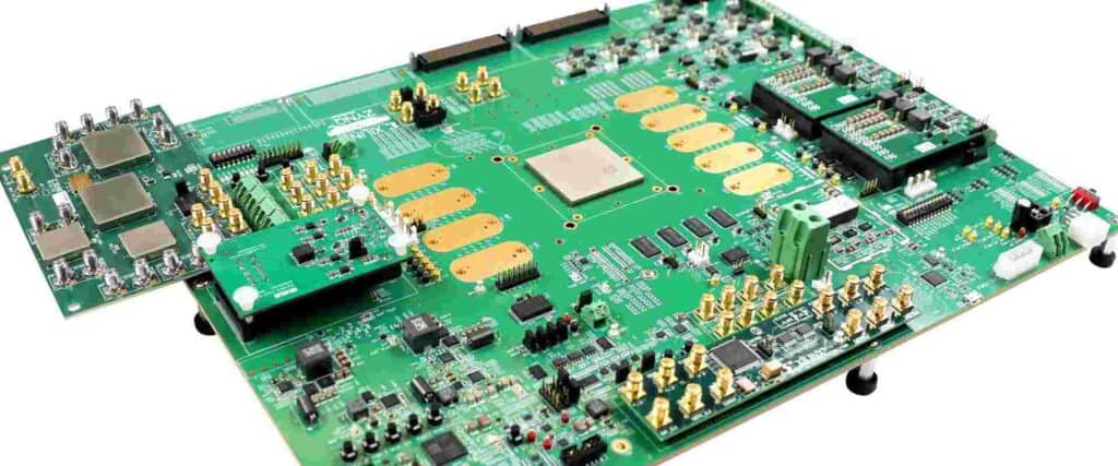
Printed circuit boards (PCBs) form the backbone of most modern electronic devices. From smartphones and laptops to industrial equipment, PCBs provide the platform to mount and interconnect electronic components using conductive tracks and pads.
The PCB assembly process involves soldering various electronic components like integrated circuits, resistors, capacitors etc. onto a PCB. Proper selection of PCB assembly components is crucial for assembling a high-quality and reliable PCB assembly. This article provides a comprehensive guide on various PCB assembly components.
PCB Assembly Components
There are several components that need to be selected and sourced for assembling a PCB assembly. Here are the most common PCB assembly components:
Printed Circuit Board (PCB)
The PCB provides the foundation for mounting and interconnecting electronic components. Key considerations for selecting PCBs:
- Number of conductive layers (single-sided, double-sided or multi-layer)
- PCB materials like FR-4, Rogers, ceramic etc.
- PCB thickness
- Copper weight (1 oz, 2 oz)
- Minimum track width and spacing
- PCB finish (HASL, immersion silver, ENIG etc.)
- Thermal reliefs – for heat dissipation
- Impedance control for high-speed signals
- PCB fabrication tolerances
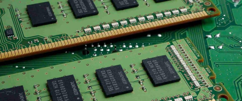
Integrated Circuits (ICs)
ICs like microprocessors, microcontrollers, memory chips, voltage regulators etc. provide the core functionality of the PCB assembly. Key considerations for selecting ICs:
- Package type – DIP, SOIC, QFP, BGA etc.
- Operating voltage, current rating, and power dissipation
- Temperature range
- Operating speed or frequency
- Interface protocols (like I2C, SPI)
- Pin count
Discrete Semiconductor Components
Discrete components like transistors, diodes, LEDs are soldered onto the PCB to provide auxiliary functions. Key considerations:
- Power or voltage or current rating
- Switching speed for transistors
- Forward voltage drop for diodes
- Package type – through-hole or SMD
Passive Components
Passive components like resistors, capacitors, and inductors are used for basic functions like current limiting, decoupling, filtering etc. Key considerations:
- Resistance, capacitance or inductance value
- Tolerance
- Voltage and power ratings
- Temperature coefficient
- SMD chip size (0402, 0603, 1206 etc.)
Connectors
Connectors allow interfacing the PCB assembly with external circuits and devices. Some common connectors are:
- Board-to-board connectors
- Board-to-cable connectors like USB, HDMI etc.
- Headers and sockets for interfacing with ribbon cables
- RF connectors like SMA, SMB, SMP, MCX, MMCX
Key considerations for connector selection include number of pins/contacts, pitch, mounting style, current rating, and mechanical locking mechanism.
Switches and Relays
Switches allow controlling circuits, while relays allow isolation between low and high power circuits. Key specifications are contact ratings, switch actuation force, and termination style.
Light Emitting Diodes (LEDs)
LEDs provide visual indicators on PCB assemblies. Key parameters are viewing angle, luminous intensity, and forward voltage drop.
Crystals and Oscillators
Crystals and oscillators provide a frequency reference to microcontrollers and integrated circuits. Important parameters are operating frequency, frequency stability, oscillator package type, and input/output waveform levels.
Heat Sinks and Fans
Heat sinks and fans help dissipate heat generated by high-power components on a PCB assembly. Key factors are thermal resistance, airflow rate (for fans), and mechanical compatibility with components like power transistors.
Spacers and Standoffs
Spacers and standoffs provide proper spacing between stacked circuit boards and assemblies. Important parameters are screw thread type, length, diameter, and materials like nylon, brass etc.
Hardware – Screws, Nuts and Washers
Various screws, nuts, washers and other hardware items are used for assembling and fastening components onto the PCB assembly.
PCB Assembly Equipment
Along with components, the right equipment is also vital for assembling PCBs efficiently:
Soldering Equipment
- Soldering irons – for manual soldering
- Reflow ovens – for soldering SMD components
- Wave soldering machines – for soldering through-hole components
- Rework stations – for desoldering and reworking defective joints
- Fume extractors – for removing harmful fumes
Software Tools
- PCB Assembly CAD tools – for assembly planning, bill of materials (BOM) generation, and pick and place file creation
- Solder paste inspection tools – for checking solder paste application
- Automated optical inspection (AOI) systems – for inspecting assembled PCBs
Hand Tools and Consumables
- Solder wire, solder paste, solder flux – soldering consumables
- Multimeter, microscope – for inspection and debugging
- Tweezers, pliers, cutters – for component handling
- Solder wick, solder sucker – for desoldering
- Isopropyl alcohol, cleaning swabs – for cleaning flux residue
Factors Impacting Component Selection
While selecting components, engineers evaluate various factors to make optimal choices:
Functional Requirements
The functionality and electrical performance needed from components based on the product specifications and architecture. For example – selecting a microcontroller with required memory, peripherals, and interfaces.
Environmental Requirements
Expected operating environment like temperature, humidity, mechanical shock. This affects component ruggedness and rating.
Size Constraints
Whether the components need to be compact to fit into small enclosures and thin devices like smartphones. This affects choices like integrated circuits packaging.
Supply Chain Considerations
Aspects like lead time, inventory availability, logistics costs, and component lifecycle need to be considered. This may require selecting alternative components.
Compliance Requirements
Necessary regulatory and safety compliances like UL, FCC emission norms that impact component selection.
Cost
Budgetary constraints on the overall PCB assembly which makes engineers optimize component costs.
By evaluating these key factors, engineers can select the most optimal PCB components for their application needs and constraints.
PCB Assembly Components Comparison Table
Here is a comparison table highlighting some key differences between common PCB assembly component categories:
| Component | Key Function | Current Rating | Power Handling | Typical Size | Common Packages |
|---|---|---|---|---|---|
| Resistors | Limit current | Low (100 mA) | Low (0.25W) | 0603, 0805 SMD | Axial leaded, SMD chip |
| Capacitors | Store charge | Low (1A) | Medium (0.5W) | 0402, 0603, 1206 SMD | Radial leaded, SMD chip |
| Inductors | Store energy in magnetic field | Medium (3A) | Medium (0.5W) | 0603, 1008 SMD | Axial leaded, SMD chip |
| Diodes | Allow current in 1 direction | Medium (1A) | Medium (500mW) | SOD-123, SOD-323 | Axial leaded |
| Transistors | Amplify/switch signals | Medium (500mA) | Medium (350mW) | SOT-23, SOT-89 | Through-hole TO-92 |
| Integrated Circuits | Process signals | Low (20mA) | Low (50mW) | QSOP, TQFP, BGA | Through-hole DIP |
PCB Assembly Process Overview
The typical assembly process flow involves the following stages:
- PCB Fabrication – Making the bare printed circuit using substrates like FR4.
- Stencil Printing – Applying solder paste on PCB pads for surface-mount components.
- Pick and Place – Mounting components onto the PCB.
- Reflow soldering – Soldering the SMD components by applying controlled heat.
- Wave soldering – Soldering leaded components by passing PCB over molten solder.
- Cleaning – Removing flux residues from post-soldered PCBs.
- Automated optical inspection – Checking for defects in solder joints, missing components etc.
- Testing– Electrical testing, burn-in testing to eliminate early component failures.
- Conformal coating – Applying protective coating for circuit protection.
- Final inspection – Visual inspection before packaging.
Meticulous attention during the assembly process is vital for assembling defect-free, high-quality PCBs. This requires using the right PCB assembly components along with robust process control.
FQA on PCB Assembly Components
What are the most commonly used PCB assembly components?
The most commonly used PCB components are:
- Passive components like resistors, capacitors and inductors.
- Integrated circuits like microcontrollers, microprocessors, memory chips etc.
- Discrete semiconductors like diodes, transistors, LEDs.
- Connectors for interfacing with peripherals.
- Crystals and oscillators for generating clock signals.
Why is component selection important in PCB assembly?
Choosing the right electronic components is critical for:
- Ensuring the assembled PCB meets the functional requirements.
- Guaranteeing components are suitable for expected electrical loads, environment, temperature etc.
- Meeting size constraints and compliance standards.
- Optimizing BOM cost by selecting cost-effective components.
What are surface mount (SMD) components?
Surface mount devices (SMD) are electronic components designed to be soldered directly onto the surface of PCBs rather than through holes. Common examples are chip resistors, capacitors and IC packages like SOIC, QFP, BGA. SMD components allow increased component density on PCBs.
How are through-hole PCB components soldered?
Through-hole components have wire leads which are inserted into holes on the PCB. The leads are soldered onto copper PCB pads, usually using wave soldering. Through-hole components provide strong mechanical bonds to PCBs.
What materials are used for fabricating PCBs?
The most common PCB substrate material is FR-4 – a composite of fiberglass and flame-retardant epoxy resin. For high frequency applications, other materials like Rogers, polyimide, Teflon, ceramic are used. Copper traces on the PCBs carry signals between components.


0 Comments