
A comprehensive guide to improve automotive PCB design!
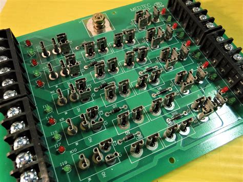
Understanding the Challenges of Automotive PCB Design
Harsh Environmental Conditions
Automotive PCBs are subjected to extreme environmental conditions, including:
– Wide temperature ranges (-40°C to +125°C)
– Vibration and shock
– Humidity and moisture
– Exposure to chemicals and fluids
These harsh conditions necessitate robust design considerations to ensure the longevity and reliability of the PCBs.
Electromagnetic Compatibility (EMC)
Automotive electronics are prone to electromagnetic interference (EMI) from various sources, such as:
– Engine ignition systems
– Power transmission systems
– Communication devices
– External sources (e.g., radio towers, other vehicles)
Effective EMC design practices are essential to minimize interference and ensure the proper functioning of electronic systems.
Space Constraints
As vehicles become more compact and feature-packed, the available space for electronic components diminishes. Automotive PCB designers must optimize board layout and component placement to accommodate tight space constraints while maintaining performance and reliability.
Cost Optimization
The automotive industry is highly competitive, and cost optimization is a critical factor in PCB design. Designers must strike a balance between performance, reliability, and cost-effectiveness by selecting appropriate materials, components, and manufacturing processes.
Best Practices for Automotive PCB Design
Component Selection
- Choose automotive-grade components that are rated for the expected environmental conditions (e.g., temperature, vibration, humidity).
- Consider using surface-mount devices (SMDs) to minimize board space and improve reliability.
- Select components with proven track records and reliable suppliers to ensure consistent quality and availability.
Board Material Selection
- Use high-quality, automotive-grade PCB materials that can withstand harsh environmental conditions.
- Consider using thermal management materials, such as metal-core PCBs or thermal vias, to dissipate heat effectively.
- Select materials with low moisture absorption and high glass transition temperature (Tg) to minimize warpage and ensure dimensional stability.
Layering and Stackup
- Implement a well-planned layer stackup to optimize signal integrity, power distribution, and thermal management.
- Use dedicated power and ground planes to minimize impedance and provide a low-inductance return path for high-speed signals.
- Consider using blind and buried vias to minimize board space and improve signal routing.
Grounding and Shielding
- Implement a solid grounding strategy to minimize EMI and ensure proper functionality of electronic systems.
- Use ground planes and grounding vias to create a low-impedance return path for high-frequency signals.
- Incorporate shielding techniques, such as copper pours or shielding cans, to protect sensitive components from EMI.
Signal Integrity and Power Integrity
- Perform signal integrity simulations to analyze and optimize high-speed signal traces.
- Implement controlled impedance routing and termination techniques to minimize reflections and signal distortion.
- Use power integrity analysis to ensure stable and clean power delivery to components.
Thermal Management
- Conduct thermal simulations to identify hot spots and optimize component placement for effective heat dissipation.
- Implement thermal management techniques, such as thermal vias, heat sinks, or thermal interface materials, to dissipate heat from critical components.
- Consider using thermal reliefs or teardrops to minimize thermal stress on component pads.
Design for Manufacturing (DFM)
- Adhere to manufacturing guidelines and constraints to ensure high yields and minimize defects.
- Implement proper component spacing, trace widths, and clearances based on the selected manufacturing process.
- Use design rule checks (DRC) and manufacturability checks to identify and resolve potential issues before production.
Testing and Validation
- Develop comprehensive testing and validation plans to verify the functionality, reliability, and performance of automotive PCBs.
- Perform environmental stress tests (e.g., temperature cycling, vibration, humidity) to ensure the PCBs can withstand harsh automotive conditions.
- Conduct EMC testing to validate the effectiveness of EMI mitigation techniques and ensure compliance with relevant standards.

Common Automotive PCB Design Challenges and Solutions
Challenge 1: Minimizing Electromagnetic Interference (EMI)
Solution:
– Implement proper grounding and shielding techniques.
– Use differential signaling for high-speed communication interfaces.
– Incorporate EMI filters and suppression components.
– Optimize component placement and routing to minimize coupling and crosstalk.
Challenge 2: Ensuring Reliable Power Distribution
Solution:
– Use dedicated power planes and grounding planes.
– Implement decoupling capacitors close to power pins of components.
– Use power integrity analysis to optimize power distribution network (PDN) design.
– Consider using voltage regulators and power sequencing techniques for stable power delivery.
Challenge 3: Designing for High-Vibration Environments
Solution:
– Use mechanically robust components and packaging (e.g., underfill, conformal coating).
– Implement strain relief techniques for connectors and cables.
– Use vibration dampening materials or mounts to isolate sensitive components.
– Perform vibration testing to validate the mechanical integrity of the PCB Assembly.
Challenge 4: Optimizing for High-Temperature Operation
Solution:
– Select components and materials with appropriate temperature ratings.
– Implement thermal management techniques (e.g., heat sinks, thermal vias, thermal interface materials).
– Optimize component placement and routing to minimize thermal coupling.
– Perform thermal simulations and testing to validate the thermal performance of the PCB.
Challenge 5: Achieving Compact and Space-Efficient Designs
Solution:
– Use high-density interconnect (HDI) techniques, such as microvias and fine-pitch components.
– Implement 3D packaging technologies, such as system-in-package (SiP) or package-on-package (PoP).
– Optimize component placement and routing to minimize board space.
– Consider using flexible or rigid-flex PCBs for space-constrained applications.

Automotive PCB Design Tools and Resources
To streamline the automotive PCB design process and ensure compliance with industry standards, designers can leverage various tools and resources:
-
PCB Design Software: Use industry-standard PCB design tools, such as Altium Designer, Cadence Allegro, or Mentor Graphics PADS, to create schematics, layout boards, and perform simulations.
-
Simulation Tools: Utilize simulation tools for signal integrity, power integrity, and thermal analysis, such as Ansys SIwave, Cadence Sigrity, or Mentor Graphics HyperLynx.
-
Component Libraries: Employ component libraries specific to automotive applications, which include verified and qualified components from trusted suppliers.
-
Design Guidelines and Standards: Refer to automotive industry standards and guidelines, such as AEC-Q100, IPC-6012DA, or ISO 26262, to ensure compliance and reliability.
-
Collaboration Platforms: Use collaboration platforms, such as Altium 365 or Cadence OrbitIO, to facilitate seamless communication and data sharing among design teams and stakeholders.

FAQ
Q1: What are the key considerations for selecting components for automotive PCBs?
A1: When selecting components for automotive PCBs, consider the following factors:
– Automotive-grade qualification (e.g., AEC-Q100)
– Temperature rating and operating range
– Vibration and shock resistance
– Moisture sensitivity level (MSL)
– Reliability and failure rate data
– Availability and long-term supply chain stability
Q2: How can I ensure electromagnetic compatibility (EMC) in automotive PCB designs?
A2: To ensure EMC in automotive PCB designs, follow these practices:
– Implement proper grounding and shielding techniques
– Use differential signaling for high-speed interfaces
– Incorporate EMI filters and suppression components
– Optimize component placement and routing to minimize coupling and crosstalk
– Perform EMC simulation and testing to validate the design
Q3: What are the common thermal management techniques used in automotive PCBs?
A3: Common thermal management techniques for automotive PCBs include:
– Using thermal vias to transfer heat from components to other layers or heatsinks
– Incorporating metal-core PCBs or thermal management materials
– Optimizing component placement and routing to minimize thermal coupling
– Implementing heatsinks, thermal interface materials, or active cooling solutions
– Performing thermal simulations and testing to validate the thermal performance
Q4: How can I optimize automotive PCB designs for manufacturing and assembly?
A4: To optimize automotive PCB designs for manufacturing and assembly, consider the following:
– Adhere to design for manufacturing (DFM) guidelines provided by the manufacturer
– Implement proper component spacing, trace widths, and clearances
– Use design rule checks (DRC) and manufacturability checks to identify and resolve issues
– Consider the assembly process and use appropriate component packaging and placement
– Communicate effectively with the manufacturing and assembly teams to address any concerns
Q5: What are the key industry standards and certifications for automotive PCBs?
A5: Some of the key industry standards and certifications for automotive PCBs include:
– AEC-Q100: Failure mechanism-based stress test qualification for integrated circuits
– IPC-6012DA: Automotive applications addendum to IPC-6012D, qualification and performance specification for rigid printed boards
– ISO 26262: Road vehicles – Functional safety
– IATF 16949: Quality management system standard for the automotive industry
– IPC-A-610: Acceptability of electronic assemblies
By understanding and adhering to these standards, automotive PCB designers can ensure the reliability, safety, and quality of their designs.
Conclusion
Designing automotive PCBs requires a meticulous approach to ensure reliability, performance, and cost-effectiveness in the face of harsh environmental conditions, electromagnetic interference, and space constraints. By following best practices, selecting appropriate components and materials, and leveraging industry-standard tools and resources, designers can create robust and efficient automotive PCB designs.
Continuous learning and staying updated with the latest advancements in automotive electronics technology is crucial for designers to stay competitive in this evolving industry. By embracing innovation and collaborating with cross-functional teams, automotive PCB designers can contribute to the development of safer, smarter, and more sustainable vehicles.