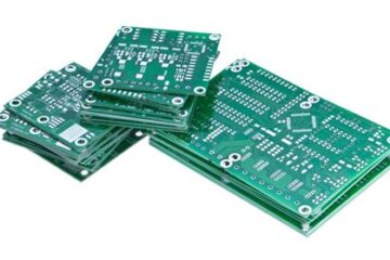
Introduction to Interface Types in Electric Circuits
In the world of electric circuits, interface types play a crucial role in ensuring proper communication and compatibility between various components. These interfaces allow different parts of a circuit to connect, exchange information, and work together seamlessly. Understanding the common interface types used in electric circuits is essential for anyone involved in designing, building, or troubleshooting electronic systems.
What are Interface Types?
Interface types refer to the standardized methods and protocols used to establish connections and facilitate communication between different components in an electric circuit. These interfaces define the physical, electrical, and logical characteristics of the connections, ensuring that components can interact effectively and reliably.
Common Interface Types
There are several common interface types used in electric circuits, each with its own unique characteristics and applications. Let’s explore some of the most widely used interface types:
1. Digital Interfaces
Digital interfaces are used to transmit digital signals between components in a circuit. These interfaces use binary digits (0s and 1s) to represent information and typically operate at specific voltage levels. Some common digital interfaces include:
1.1 UART (Universal Asynchronous Receiver/Transmitter)
UART is a widely used serial communication interface that allows two devices to exchange data asynchronously. It uses two signal lines: TX (transmit) and RX (receive). UART is commonly found in microcontrollers, modems, and other communication devices.
1.2 SPI (Serial Peripheral Interface)
SPI is a synchronous serial communication interface that enables high-speed data transfer between a master device and one or more slave devices. It uses four signal lines: MOSI (Master Out Slave In), MISO (Master In Slave Out), SCK (Serial Clock), and SS (Slave Select). SPI is often used for connecting sensors, displays, and memory devices to microcontrollers.
1.3 I2C (Inter-Integrated Circuit)
I2C is a synchronous serial communication interface that allows multiple devices to communicate using just two signal lines: SDA (Serial Data) and SCL (Serial Clock). Each device on the I2C bus has a unique address, enabling the master device to selectively communicate with specific slave devices. I2C is commonly used for connecting sensors, EEPROMs, and other low-speed peripherals.
| Interface | Data Lines | Clock Lines | Speed | Topology |
|---|---|---|---|---|
| UART | TX, RX | – | Moderate | Point-to-Point |
| SPI | MOSI, MISO | SCK | High | Master-Slave |
| I2C | SDA | SCL | Low | Multi-Master, Multi-Slave |
2. Analog Interfaces
Analog interfaces are used to transmit continuous, varying signals between components in a circuit. These interfaces deal with signals that can take on any value within a specific range. Some common analog interfaces include:
2.1 Voltage Signals
Voltage signals are the most basic form of analog interface. They represent information by varying the voltage level of a signal line. Voltage signals can be used to transmit sensor readings, control signals, or any other continuous data.
2.2 Current Signals
Current signals use the variation in electric current to represent information. They are less common than voltage signals but offer some advantages, such as better noise immunity and the ability to transmit signals over long distances.
2.3 PWM (Pulse Width Modulation)
PWM is a technique used to encode analog signals into a digital format. It involves modulating the width of pulses in a square wave signal to represent the analog value. PWM is commonly used for controlling the brightness of LEDs, the speed of motors, or the position of servos.
3. Power Interfaces
Power interfaces are used to supply electrical power to components in a circuit. These interfaces ensure that components receive the appropriate voltage and current levels to operate correctly. Some common power interfaces include:
3.1 DC Power
DC (Direct Current) power interfaces provide a constant voltage and current to components. They are commonly used for powering microcontrollers, sensors, and other low-power devices. DC power can be supplied through batteries, power adapters, or voltage regulators.
3.2 AC Power
AC (Alternating Current) power interfaces supply power in the form of a sinusoidal waveform. AC power is commonly used for high-power applications, such as household appliances and industrial equipment. AC power interfaces often involve transformers, rectifiers, and other power conditioning components.
4. Wireless Interfaces
Wireless interfaces allow components to communicate and exchange data without the need for physical connections. These interfaces use electromagnetic waves to transmit signals over the air. Some common wireless interfaces include:
4.1 Bluetooth
Bluetooth is a short-range wireless communication protocol that enables devices to exchange data over short distances. It operates in the 2.4 GHz frequency band and is commonly used for connecting peripherals, such as headphones, keyboards, and smart devices.
4.2 Wi-Fi
Wi-Fi is a wireless networking technology that allows devices to connect to the internet or communicate with each other over longer distances. It operates in the 2.4 GHz and 5 GHz frequency bands and is widely used in homes, offices, and public spaces.
4.3 RF (Radio Frequency)
RF interfaces use radio waves to transmit signals between components. They can operate at various frequencies and are used for a wide range of applications, including remote controls, wireless sensors, and long-range communication systems.
Choosing the Right Interface Type
When designing an electric circuit, it’s essential to choose the appropriate interface types based on the specific requirements of the application. Consider factors such as data rate, distance, power consumption, and compatibility with other components in the system.
Here are some guidelines to help you select the right interface type:
-
Data Rate: Consider the amount of data that needs to be transferred and the required speed of communication. High-speed interfaces like SPI are suitable for applications that require fast data transfer, while slower interfaces like I2C are sufficient for low-speed peripherals.
-
Distance: Take into account the distance between components and the environment in which the circuit will operate. For short distances, wired interfaces like UART or I2C can be used, while wireless interfaces like Bluetooth or Wi-Fi are better suited for longer distances or when physical connections are not feasible.
-
Power Consumption: Evaluate the power requirements of the components and choose interfaces that are energy-efficient. Low-power interfaces like I2C and SPI are preferred for battery-powered devices, while high-power interfaces like AC power are suitable for mains-powered equipment.
-
Compatibility: Ensure that the chosen interface types are compatible with the components in the circuit. Check the specifications and datasheets of the components to verify their supported interface types and electrical characteristics.
-
Scalability: Consider the future expansion and scalability of the system. Choose interface types that can accommodate additional components or allow for easy integration with other systems.

Conclusion
Interface types are a fundamental aspect of electric circuits, enabling communication and compatibility between various components. Understanding the common interface types, such as digital interfaces (UART, SPI, I2C), analog interfaces (voltage, current, PWM), power interfaces (DC, AC), and wireless interfaces (Bluetooth, Wi-Fi, RF), is crucial for designing and working with electronic systems.
When selecting interface types, consider factors like data rate, distance, power consumption, compatibility, and scalability to ensure optimal performance and reliability of the electric circuit.
By mastering the concepts of interface types, you’ll be well-equipped to design, troubleshoot, and innovate in the world of electric circuits.
Frequently Asked Questions (FAQ)
-
What is the difference between synchronous and asynchronous interfaces?
Synchronous interfaces, such as SPI and I2C, use a shared clock signal to synchronize the communication between components. Data transfer occurs at specific clock intervals. On the other hand, asynchronous interfaces, like UART, do not rely on a shared clock signal. Instead, they use start and stop bits to indicate the beginning and end of each data packet. -
Can I use multiple interface types in the same electric circuit?
Yes, it’s common to use multiple interface types within a single electric circuit. Different components may have different communication requirements, and using a combination of interface types allows for optimal performance and functionality. However, it’s important to ensure proper compatibility and to use appropriate level-shifting or signal conditioning techniques when necessary. -
How do I determine the appropriate data rate for an interface?
The appropriate data rate for an interface depends on the specific requirements of the application. Consider the amount of data that needs to be transferred and the timing constraints of the system. Refer to the datasheets and specifications of the components to determine their supported data rates. It’s important to choose a data rate that meets the performance requirements while considering factors like power consumption and signal integrity. -
What are the advantages of using wireless interfaces in electric circuits?
Wireless interfaces offer several advantages in electric circuits. They eliminate the need for physical connections, allowing for greater flexibility in system design and layout. Wireless interfaces enable remote communication and control, making it possible to interact with components from a distance. They also simplify installation and reduce the overall wiring complexity of the system. However, wireless interfaces may have limitations in terms of range, security, and power consumption compared to wired interfaces. -
How do I ensure proper signal integrity when using high-speed interfaces?
Ensuring signal integrity is crucial when using high-speed interfaces like SPI or high-frequency wireless interfaces. To maintain signal integrity, consider the following practices: - Use proper termination techniques, such as impedance matching and termination resistors, to minimize reflections and signal distortions.
- Keep signal traces as short as possible and avoid excessive bends or vias to reduce parasitic effects.
- Use appropriate shielding and grounding techniques to minimize electromagnetic interference (EMI) and crosstalk.
- Adhere to the recommended layout guidelines and follow best practices for high-speed PCB design.
- Use signal conditioning techniques, such as filtering and equalization, to compensate for signal degradation over long distances or through noisy environments.
By understanding and applying these principles, you can ensure reliable and error-free communication in your electric circuits.


0 Comments