PCBA
Printed Circuit Board Assembly Process – The comprehensive Guide!
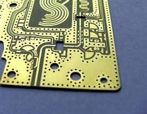
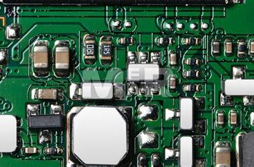
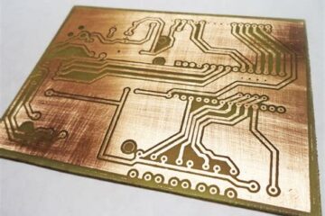
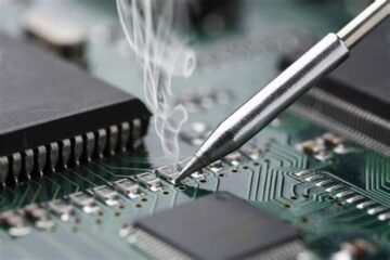
Introduction to PCB Assembly Printed Circuit Board (PCB) assembly is a crucial process in the manufacturing of electronic devices. It involves the placement and soldering of various components onto a PCB to create a functional circuit. In this comprehensive guide, we will delve into the intricacies of the PCB assembly process, covering everything from the basics to advanced techniques. What is a Printed Circuit Board? A Printed Circuit Board, or PCB, is a flat board Read more…